khansaab21
Advanced Member level 4
Help with IR2112/3
Hello there.
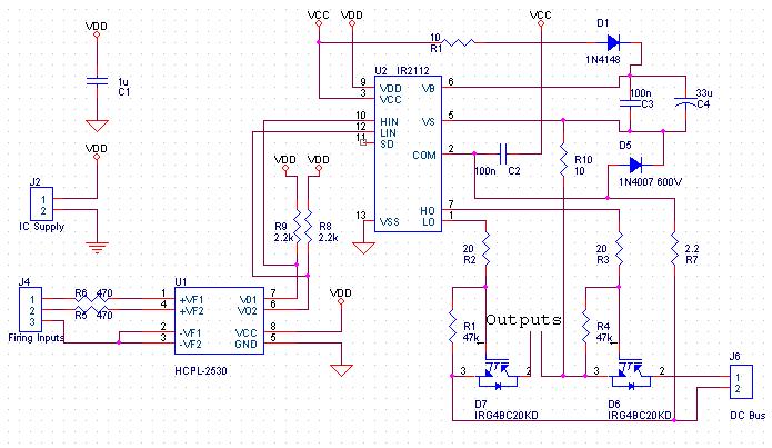
I am using IR2112 (gate driver) for driving the half bridge of my 3 phase inverter. I have figured out the boot strap component ratings and gate turn on/off resistor ratings as according to my application needs. Following are the things I dont understand.
1) The maximum motor current is around 1.5Amps and it operates on 220Vac (name plate parameter). Does this factor have anything to do with wattage ratings of the bootstrap and other gate driving components?? I mean, are quarter or half watt capacitor and resistors are good enough or I have to properly evaluate their power ratings??
2) The power components are IGBT's. On data sheet it is listed that 'Vge - th' is maximum 7V. Does this mean I can not drive the gate at 15V (or geater than 7V in general)
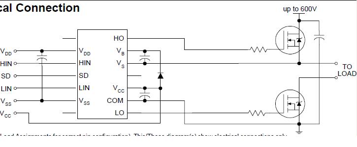
3) What should be the value of capacitor attached to the supply pins of low side supply?? Is it the same as that of boot strap capacitor or is there any way to evaluate its value?? (Pic is attached)
Hello there.
I am using IR2112 (gate driver) for driving the half bridge of my 3 phase inverter. I have figured out the boot strap component ratings and gate turn on/off resistor ratings as according to my application needs. Following are the things I dont understand.
1) The maximum motor current is around 1.5Amps and it operates on 220Vac (name plate parameter). Does this factor have anything to do with wattage ratings of the bootstrap and other gate driving components?? I mean, are quarter or half watt capacitor and resistors are good enough or I have to properly evaluate their power ratings??
2) The power components are IGBT's. On data sheet it is listed that 'Vge - th' is maximum 7V. Does this mean I can not drive the gate at 15V (or geater than 7V in general)
3) What should be the value of capacitor attached to the supply pins of low side supply?? Is it the same as that of boot strap capacitor or is there any way to evaluate its value?? (Pic is attached)