Continue to Site

Welcome to EDAboard.com

Welcome to our site! EDAboard.com is an international Electronics Discussion Forum focused on EDA software, circuits, schematics, books, theory, papers, asic, pld, 8051, DSP, Network, RF, Analog Design, PCB, Service Manuals... and a whole lot more! To participate you need to register. Registration is free. Click here to register now.

Multisim Simulation a FM transmitter drom E-desing

Status
Not open for further replies.

Flying_carlos

Newbie level 3
Joined
May 13, 2006
Messages
3
Helped
0
Reputation
0
Reaction score
0
Trophy points
1,281
Activity points
1,298
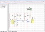
I'm a newbie with multisim and was trying to see a FM circuit posted by E-design. I got a curios behavior . The circuit alone doesn't oscillate until I add a Spectrum analyzer instrument and a probe (probe1). Taking out the SA the circuit oscillate around KHZ .
I really don't understand what happen.


Here is the circuit
 

Attachments

  • Fm Transmitter E-Design.jpg
    Fm Transmitter E-Design.jpg
    345.8 KB · Views: 224

Your circuit needs a load at the output. Place a 1k resistor to the ground from the SA and Probe joint (right side of C6).
 

Your circuit needs a load at the output. Place a 1k resistor to the ground from the SA and Probe joint (right side of C6).

I did it, but isn't still working. Probe2 is ~50KHz and Probe1 ~550HZ
 

Make sure your Initial time step (TSTEP) under Simulate-Interactive Simulation Settings is small enough. For this example must be ≤ 1nS otherwise oscillations won't start.
 
I need help........... I dont understand how this circuit works! What is the signal??
 

Status
Not open for further replies.

Similar threads

Part and Inventory Search

Welcome to EDABoard.com

Sponsor

Back
Top