Welcome to our site! EDAboard.com is an international Electronics Discussion Forum focused on EDA software, circuits, schematics, books, theory, papers, asic, pld, 8051, DSP, Network, RF, Analog Design, PCB, Service Manuals... and a whole lot more! To participate you need to register. Registration is free. Click here to register now.
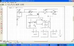
It seems to me that you are going to burn up a power FET
unless those batteries have a high series resistance (in which
case, cook the battery instead). And the complexity probably
means you'd see less assembly cost by using a high side
power MOSFET driver IC, than those discretes. The clock,
you could get as-shown or use a LM555.
Ok, what is the current capability of the 100V source ?
that is what will determine whether this circuit survives or not !!
I get the idea of pulse charging (is it lead acid ?)......
even so does it really need 100V ?
You had better keep a watch on the battery temperature as well....
pulse charging could be a superior way to recharge batteries, either when they are at very low SOC or for float charge......I have doubts atm for bulk charge.
you can put an inductor in series to battery to limit the di/dt rate when the
mosfet switches on....
actualy i have now decided not to use that ckt, because practically this ckt is proven with resistive load of 15 amp 100v, but for this battery load where current is not predictable ,i have studied different options, after than i came to conclusion i will use mosfet driver ir 2110,or 2118, i will use current sensing resistor and keep the current in limit, i will use inrush current limiter, 555 pwm controlled signal ,and appropriate snubber ckt, i have found different ckts, now i am just optimising it
This site uses cookies to help personalise content, tailor your experience and to keep you logged in if you register.
By continuing to use this site, you are consenting to our use of cookies.