milvapp
Member level 5
- Joined
- Apr 17, 2010
- Messages
- 88
- Helped
- 3
- Reputation
- 6
- Reaction score
- 2
- Trophy points
- 1,288
- Location
- chania greece
- Activity points
- 1,882
Hi everyone,
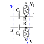
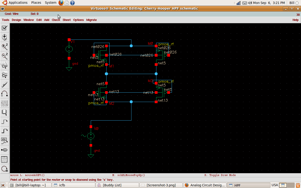
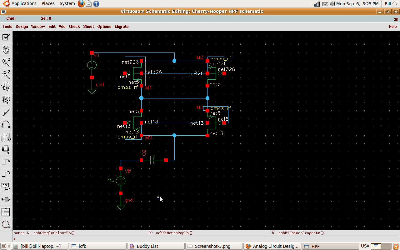
I want to design and simulate a 1st order 200 KHz HPF in Cadence
 ,
,
but instead of the regular R I use a subthreshold PMOS resistor
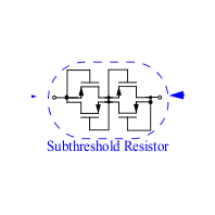
(because the R value needed for this filter is about 1.6MΩ and in
terms of space is too big for 90nm CMOS technology).As a result
Vbias is needed to bias the pmos resistor in order to get the desired R value.
The problem is that:
a)
Whenever I run AC analysis at the circuit above(without the capacitor)everything works fine and the subthreshold resistor has the desired value 1.6ΜΩ.But..
b)
When I add the C to implement the filter the DC bias has no effect at all.It is like the upper part od the resistor is connected straight to the ground and as a result it ruins the desired value of the resistor(reaching about 32MΩ)which makes the filter have a 10 KHz cutoff frequency.
Sorry if I got too long,I just wanted to be perfectly understood.
These are the values.
W=30uM
L=200nM
Vbias=0.24 V
ACmag=1V
(desired)Res=1.6MΩ
cap=0.5pF
Any help will be very appreciated,
Thank you in advance
I want to design and simulate a 1st order 200 KHz HPF in Cadence
but instead of the regular R I use a subthreshold PMOS resistor
(because the R value needed for this filter is about 1.6MΩ and in
terms of space is too big for 90nm CMOS technology).As a result
Vbias is needed to bias the pmos resistor in order to get the desired R value.
The problem is that:
a)
Whenever I run AC analysis at the circuit above(without the capacitor)everything works fine and the subthreshold resistor has the desired value 1.6ΜΩ.But..
b)
When I add the C to implement the filter the DC bias has no effect at all.It is like the upper part od the resistor is connected straight to the ground and as a result it ruins the desired value of the resistor(reaching about 32MΩ)which makes the filter have a 10 KHz cutoff frequency.
Sorry if I got too long,I just wanted to be perfectly understood.
These are the values.
W=30uM
L=200nM
Vbias=0.24 V
ACmag=1V
(desired)Res=1.6MΩ
cap=0.5pF
Any help will be very appreciated,
Thank you in advance