bwana1
Junior Member level 3
Hi all,
HFSS full book 10 is a very useful font of examples to understand and manage HFSS software. As I found quite different behaviour with some models of mine between HFSS and CST studio (please look at another post of mine), I decided to cross test them with a model with known behaviour. So I chose the example # 5.1, UHF probe, that was close to my design.
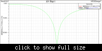
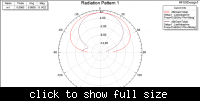
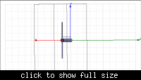
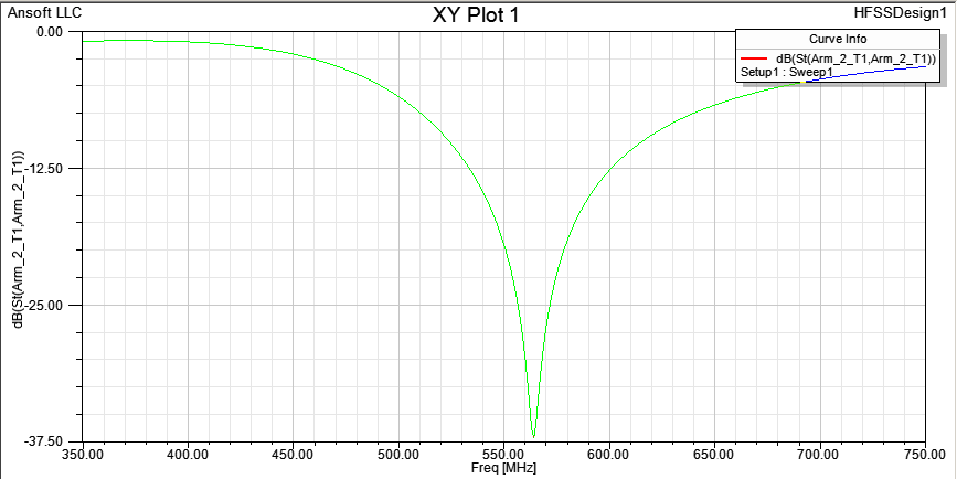
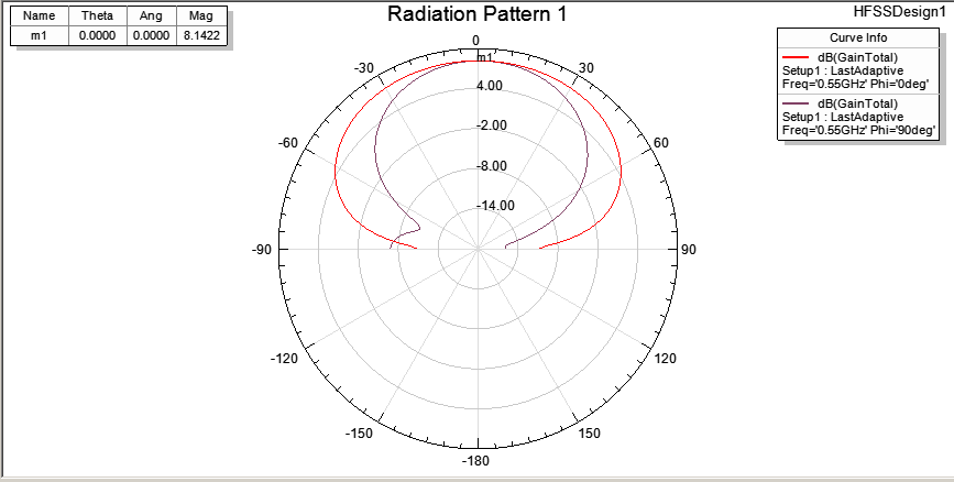
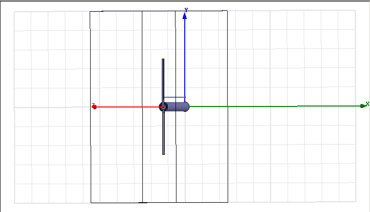
When I simulated it with HFSS11, at a first glance all was as in the book, but a deeper sight showed that S11 plot hit its minimum some 12-15 MHz higher, around 565-570 MHz instead of the 550 in the book example, and at a sensibly different depth. While the book gives a dip around -23.5 dB, I obtained either a -34.5 dB or a -17.5 dB depending on whether or not I checked to renormalize all modes for post processing. Smith chart, on the contrary, was compatible though it wasn't so easy to compare as it was plotted on a different scale. I have to say that I have tried not only the driven terminal solution as indicated in the book, but also the driven modal one, that yielded the -17.5 dB value @ 55 MHz peak , closer to expected results, checking for un-normalized results and defining a mode line from inner ring inner radius to centre pin radius. I took this way because the book defined the port in a different way than allowed for HFSS 11, so that I wasn’t sure which one were better. But anyway I couldn’t find any setting that exactly gave the book results. I have also tried different boundary settings, at first following the book, declaring a copper infinite ground plane plus the normal boundaries, then without it, setting the boundary backplane as pec and all other faces as radiating. I have had a warning but no errors. I have then repeated all this on a workstation of a friend of mine that has HFSS12 installed with the same results. So I’m asking if someone else faced the same problem or can run the same simulation to confirm my results. I attach here some screenshot of my simulation. I can also upload the hfss10 full book, that can turn useful to many people, but only if requested of it, and in the proper forum.
Of course I didn’t yet perform any simulation on CST studio suite due to the uncertainty of my present results. Anyway I fear a problem on it on defining the ground plane, because declaring Zmin side as perfect E would lend to port short-circuit. Not declaring it implies not connecting to ground the ground pin. A possible brute-force solution could be to define a very large, very thin cylinder at the probe port end as a finite ground plane, a barbaric solution…Some better ideas please?
...Hmmm... My posts have a very high audience, lately...
HFSS full book 10 is a very useful font of examples to understand and manage HFSS software. As I found quite different behaviour with some models of mine between HFSS and CST studio (please look at another post of mine), I decided to cross test them with a model with known behaviour. So I chose the example # 5.1, UHF probe, that was close to my design.
When I simulated it with HFSS11, at a first glance all was as in the book, but a deeper sight showed that S11 plot hit its minimum some 12-15 MHz higher, around 565-570 MHz instead of the 550 in the book example, and at a sensibly different depth. While the book gives a dip around -23.5 dB, I obtained either a -34.5 dB or a -17.5 dB depending on whether or not I checked to renormalize all modes for post processing. Smith chart, on the contrary, was compatible though it wasn't so easy to compare as it was plotted on a different scale. I have to say that I have tried not only the driven terminal solution as indicated in the book, but also the driven modal one, that yielded the -17.5 dB value @ 55 MHz peak , closer to expected results, checking for un-normalized results and defining a mode line from inner ring inner radius to centre pin radius. I took this way because the book defined the port in a different way than allowed for HFSS 11, so that I wasn’t sure which one were better. But anyway I couldn’t find any setting that exactly gave the book results. I have also tried different boundary settings, at first following the book, declaring a copper infinite ground plane plus the normal boundaries, then without it, setting the boundary backplane as pec and all other faces as radiating. I have had a warning but no errors. I have then repeated all this on a workstation of a friend of mine that has HFSS12 installed with the same results. So I’m asking if someone else faced the same problem or can run the same simulation to confirm my results. I attach here some screenshot of my simulation. I can also upload the hfss10 full book, that can turn useful to many people, but only if requested of it, and in the proper forum.
Of course I didn’t yet perform any simulation on CST studio suite due to the uncertainty of my present results. Anyway I fear a problem on it on defining the ground plane, because declaring Zmin side as perfect E would lend to port short-circuit. Not declaring it implies not connecting to ground the ground pin. A possible brute-force solution could be to define a very large, very thin cylinder at the probe port end as a finite ground plane, a barbaric solution…Some better ideas please?
...Hmmm... My posts have a very high audience, lately...
Last edited: