Continue to Site

Welcome to EDAboard.com

Welcome to our site! EDAboard.com is an international Electronics Discussion Forum focused on EDA software, circuits, schematics, books, theory, papers, asic, pld, 8051, DSP, Network, RF, Analog Design, PCB, Service Manuals... and a whole lot more! To participate you need to register. Registration is free. Click here to register now.

Ask help for corners simulation in cadence spectre

Status
Not open for further replies.

iiiiisland

Newbie level 5
Joined
Jun 19, 2008
Messages
8
Helped
0
Reputation
0
Reaction score
0
Trophy points
1,281
Activity points
1,338
Hello,
I want to use corners to simulate circuit in different technics, like tt,ff,ss,etc.
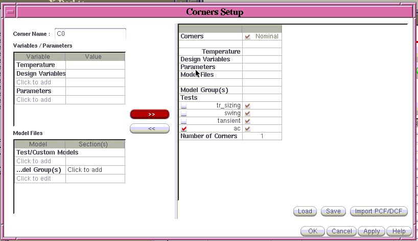
But many items under the corner window is dark, which means there are some file unsetup, I guess.
Is there any body know such situation? what files I need to setup in spectre before I run corners simulation?
THX a lot!
 

Hi,
You need some special files. Only fab can provide them for you.
 

It depends what is your design kit.

If it's a commercial design kit, AdvaRes is right. You have to talk to the fab. Or you have to read their User's quide.

I used one particular Fab, and they did not supply the setup file, but they had the user guide, which talk about how you can set the environment.

I hope this help you.
 

AdvaRes and newmedia,
Thank you!
The problem is I can do ss ff etc. simulation if I change the items under model libraries frequently. I want to do the corners simulation under the tools item in ADE Cadence because I want to see the results of different corners simulation in one time. I had read the Cadence user guide and it says "if you have defined a set of customization files to be loaded automatically, the Cadence Analog Coners Analog window appears". So I want to know how to define the set of customization files, and what files they are.

THX a lot!
 

Hello,

You have to add the corners first.


Click "Click to add corner". After this, you will see a corner definition dialog. Set your corners.


When you simulate, select all corners, if you want to simulate them all.

Thank you,
Newmedia


If it was helpful, please click "helpful!".
 

Hello,

You have to add the corners first.


Click "Click to add corner". After this, you will see a corner definition dialog. Set your corners.


When you simulate, select all corners, if you want to simulate them all.

Thank you,
Newmedia

If it was helpful, please click "helpful!".

Thank you! Newmedia
I know what you mean to tell, but in my situation the bar which shows commands like Add Corner, Add Variable, Copy Corner etc. is gray. I cannot do any simulation.
So I am puzzle if I missed some setup files and the .cdsinit file doesn't do any customization.
Besides, I want to know how to define the customization files.

Thank you so much!
 

Hello,

I don't think the .cdsinit is doing that kind of thing.

You have the license for ADE XL and GXL? If you don't have the license, that can be a good answer. (However I'm not 100% sure. )

I think there are two solutions right now.

1) Generate the netlist and use Hspice or Spectre to simulate the circuit. When you do that, you can use sweep or alter statement. And then check the results. This looks a little cumbersome, but it always works.

2) File a service request to Cadence or PDK company. Explain your situation; your menues are grayed out.

Thank you,
Newmedia
 

Status
Not open for further replies.

Part and Inventory Search

Welcome to EDABoard.com

Sponsor

Back
Top