Continue to Site

Welcome to EDAboard.com

Welcome to our site! EDAboard.com is an international Electronics Discussion Forum focused on EDA software, circuits, schematics, books, theory, papers, asic, pld, 8051, DSP, Network, RF, Analog Design, PCB, Service Manuals... and a whole lot more! To participate you need to register. Registration is free. Click here to register now.

LM629 RESET Circuit!!! Helppp

Status
Not open for further replies.

sbl

Newbie level 4
Joined
Jul 21, 2010
Messages
6
Helped
0
Reputation
0
Reaction score
0
Trophy points
1,281
Activity points
1,324
Hi,
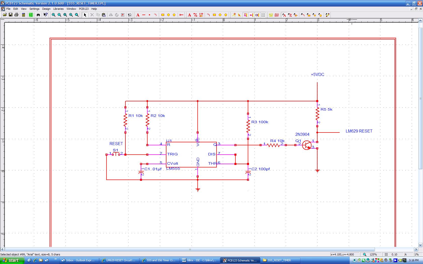
I need to connect a Reset circuit to my controller LM629 which is used to control a dc motor, but i have a problem with the reset pin(RST) 'cause don't know what a circuit to use. It's told to me that i can use timer 555 but i dont' know how :( can someone help mee,pls?!
 

Hi sbl,

You can make a one shot or monostable pulse with the 555.
Power supply is 5VDC
Pulse needs to be at least 8 clock periods wide.

http://www.kpsec.freeuk.com/555timer.htm

You then need to invert the output with a 2N3904 NPN transistor
See "NPN Common Emitter Switch here:

http://hyperphysics.phy-astr.gsu.edu/hbase/electronic/transwitch.html

Use 10k for Rb and 5k for Rc. Connect output of 555 to Rb and take negative pulse
output from collector of 2N3904.
Make sure to breadboard and test first.

Regards,
Scanman
 

Thanks for your answer Scanman :)
I will do that but first wonna ask you whether my circuit is correct.I realised a circuit with timer555 Astable and tested it in Proteus - ISIS but without LM629 because there is no proteus model of LM629:( can it be done with such a curcuit?
 

Hi sbl,

Circuit looks good but is in astable or oscillator mode.
I imagine you will be connecting a pushbutton to the trigger input (pin 2).
The output of 555 is normally low with the timed pulse at the high (+V level).
The LM629 requires it's reset to be held high and pulsed low for minimum 8 clock
cycles. You will still need the NPN transistor inverter for correct output.

Cheers,
Scanman
 

ok Scanman, I rely on you and think that I have to do your circuit :) but can you tell me how do we determine min 8 clock?!!! I know that it have to be done but how. I think 8x1.5ms, or not?!:?: And I don't understand "The output of 555 is normally low with the timed pulse at the high (+V level)" What is the NPN transistor about? Why do I have to invert the output?

Thanks for your help :)
 

Hi sbl,

Can you please answer these questions:

Is the LM629 in a commercial unit or is this an experimental circuit?
Is the reset pin connected to something now in circuit?
What is the clock frequency?

Look at page 5 on LM629 data sheet. It shows the reset level as "active low".
This means the voltage on the reset pin must be held high (+Vcc) and momentarily
pulsed low (gnd) for a minimum time of 8 clock periods.

Regards,
Scanman
 

I'm doing this circuit now and
I will just simulate it nothing else.The reset pin isn't connected to anything. The clock frequency is 4MHz.
 

So the minimum pulse width is 2 us. Which is 20 pf cap and 100k resistor.
I don't know if 555 will even do this short a pulse ?
You can probably go with a longer duration pulse with no problems.
I could try building and testing it if I can find a 555 in my junkbox :D

scanman

Added after 1 hours 4 minutes:

This is what I had in mind:


scanman
 

    sbl

    Points: 2
    Helpful Answer Positive Rating
Hi Scanman,

Thank you for the circuit :) I will test it . But there is something that isn't very clear - how did you determine the pulse width?

Regards,
sbl

Added after 2 hours 7 minutes:

Scanman, I understood about the puls width but with your help :) thankss..
 

Status
Not open for further replies.

Similar threads

Part and Inventory Search

Welcome to EDABoard.com

Sponsor

Back
Top