Continue to Site

Welcome to EDAboard.com

Welcome to our site! EDAboard.com is an international Electronics Discussion Forum focused on EDA software, circuits, schematics, books, theory, papers, asic, pld, 8051, DSP, Network, RF, Analog Design, PCB, Service Manuals... and a whole lot more! To participate you need to register. Registration is free. Click here to register now.

How does a TV CAN-Tuner work ?

Status
Not open for further replies.

LNA

Member level 3
Joined
Nov 19, 2009
Messages
64
Helped
0
Reputation
0
Reaction score
0
Trophy points
1,286
Activity points
1,735
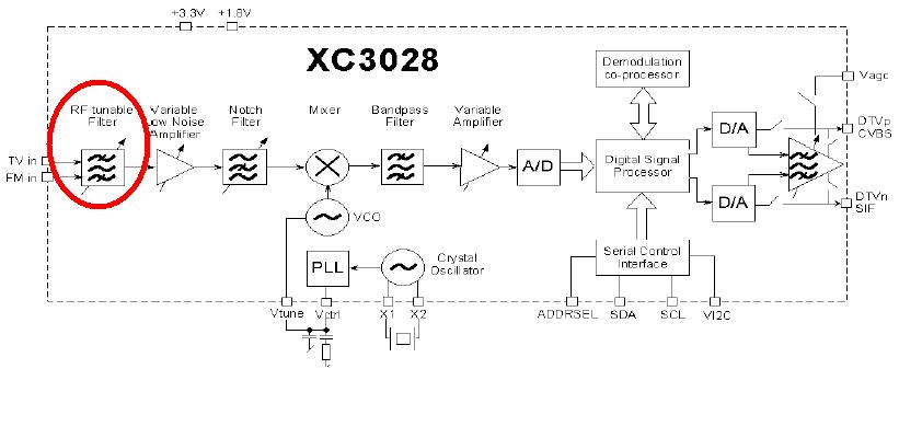
can someone help me in understanging how TV can-tuner works?
Does it tune for every channel, or for multi-channel?
Is it electronic tuned or mechanic tuned?
Is there a RF switch for every tuned channel?
Thanks,
 

TV CAN-Tuner

some background I found, but no much detail

...One of the most visible features inside a TV set is the metal can enclosure that contains the tuner. Of course, the tuner is the front end that includes the RF filters and low-noise amplifier (LNA) fed by the antenna or cable connection, the mixer, the local oscillator (LO) for channel selection, and some initial interface (IF) amplification and filtering, usually with a surface acoustic wave (SAW) filter...
 

Re: TV CAN-Tuner

ok now that we have confirmed what you are talking about :)

just call it a TV tuner module ... can-tuner... had us all guessing ;)

the majority of them are electronically tuned. 3 of the pins are for the 3 bands (VHF-L VHF-H and UHF) tuning voltage supply. The tuning voltage range is usually 0 - 30V ie. 0V = lowest freq in that band, to 30V = highest freq in that band

Other pins will be for IF out, B+ supply and AFC, maybe another couple of things
look on the tuner module or on the PCB the pin outs are usually labelled

cheers
Dave N

Added after 13 minutes:

further to my previous comments.....

on the much older TV's and VCR's there were individual trimpot resistors
say ~ 8 of them that you would individually adjust for each channel position.
they provided the set voltage for that channel that was switched to.

in the newer TV's etc.... those tuning voltage control settings for each tuned channel are stored in the processor/flash memory chip and when accessed switch the appropriate voltage to the appropriate band tuning input on the tuner module.

Dave
 

Re: TV CAN-Tuner

Thanks, Dave. I feel better, but still a lot questions,

I think that you confirmed the LO tuning. There should be a RF tunable filter in the front for every channel, with ~5MHz bandwidth, right?

How does the RF filter work in older TV? Are they mechaniclly tuned? Is there RF switch for channel switching?

What kind of performnace of these RF filters, i.e. typical adjacent channels rejection and insertion loss?

davenn said:
ok now that we have confirmed what you are talking about :)

just call it a TV tuner module ... can-tuner... had us all guessing ;)

the majority of them are electronically tuned. 3 of the pins are for the 3 bands (VHF-L VHF-H and UHF) tuning voltage supply. The tuning voltage range is usually 0 - 30V ie. 0V = lowest freq in that band, to 30V = highest freq in that band

Other pins will be for IF out, B+ supply and AFC, maybe another couple of things
look on the tuner module or on the PCB the pin outs are usually labelled

cheers
Dave N

Added after 13 minutes:

further to my previous comments.....

on the much older TV's and VCR's there were individual trimpot resistors
say ~ 8 of them that you would individually adjust for each channel position.
they provided the set voltage for that channel that was switched to.

in the newer TV's etc.... those tuning voltage control settings for each tuned channel are stored in the processor/flash memory chip and when accessed switch the appropriate voltage to the appropriate band tuning input on the tuner module.

Dave
 

Re: TV CAN-Tuner

Some schematics for illustration. First one is a 60th tube vhf tuner. It has
a rotated contact "drum" with 11 sets inductors for each individual channel


Second is a 60th uhf tuner. It's mechanical tuned by a multi varcap.


Finally a cap diode tuned 70th multiband tuner. It's using a pin diode
attenuator at the input and diodes for band switching


Newer devices are not so much different from the latter. They usually have dual gate MOSFET amplifier transistors,
but still cap diode tuning. Some have individual amplifier channels for VHF (CH 2-4), VHF (CH 5-12) and UHF.
Oscillator/mixer stage use often ICs.
 

TV CAN-Tuner

What's the typical performance of adjacents channel rejection for newer TV tuners?

Added after 5 minutes:


Found some silicon tuner ICs. Is there any separate silicon tunable filter avaliable on market? Not the whole IC.
 

TV CAN-Tuner

Because it's a superhet receiver, the adjacents channel rejection is mainly defined by the IF filter, not the tuner module.
The tuned input filter is responsible for the foreign channel large signal strength.

There are no "silicon tunable filters". Single chip receivers are either using tuned LC filters or operating as wideband
superhet receiver with IF selection only.
 

Re: TV CAN-Tuner

LNA said:
Thanks, Dave. I feel better, but still a lot questions,

I think that you confirmed the LO tuning. There should be a RF tunable filter in the front for every channel, with ~5MHz bandwidth, right?

No, Each Band, on the tuner module (VHF-L,VHF-H,UHF), are just 3 separate wideband receivers across each of those bands

LNA said:
How does the RF filter work in older TV? Are they mechaniclly tuned? Is there RF switch for channel switching?

Older TV's how old ? Valve with rotating banks of L's and C's (see FvM's cct) or semiconductor with tuner module ?
all the colour TV's from the 1970's onwards that used tuner modules used the trimmer resistor style I described above, in one form or another, untill programmable IC's took over the process.
There's next to no filtering on the front end of the tuner, hence why they suffer from all sorts of interference from other RF sources, see cct that FvM posted, its pretty minimal. And what there is is not tunable as such they are fixed lumped L's and C's

All modern tuner modules I have delt with have onboard LO's. That is, there is NO external LO signal fed to the tuner module. Tuning voltage in, IF, AFC out

Dave
 

Re: TV CAN-Tuner

FvM said:
Because it's a superhet receiver, the adjacents channel rejection is mainly defined by the IF filter, not the tuner module.
The tuned input filter is responsible for the foreign channel large signal strength.

There are no "silicon tunable filters". Single chip receivers are either using tuned LC filters or operating as wideband
superhet receiver with IF selection only.

I found this from a single chip TV receiver vendor. There is no detail avaliable from their web. But it looks like a tunable RF filter to me, channel filter? or band filter?
 

TV CAN-Tuner

The vendor says "wideband filter", most likely a variable active filter. The xceive products are different from common silicon tuner chips.
 

Re: TV CAN-Tuner

LNA said:
I found this from a single chip TV receiver vendor. There is no detail avaliable from their web. But it looks like a tunable RF filter to me, channel filter? or band filter?

It's a tracking filter.This filter select the desired channel and prevent the LNA from adjacent channel interference and other interefere sources.
It consists of a switched capacitor bank and probably bonding inductances.By digitally selecting proper capacitor value, inductance will be resonated with this capacitor at the center of the desired frequency.
 

Re: TV CAN-Tuner

FvM said:
The vendor says "wideband filter", most likely a variable active filter. The xceive products are different from common silicon tuner chips.

The vendor also says "Programmable channel filter".

I think active filter is for lower frequency, like kHz, but correct me is I was wrong.

What's the difference you see on this xceive tuner?
 

TV CAN-Tuner

Active filters can be realized up to GHz, particularly on-chip. But related to the said device it's just a guess.

The difference is in the variable filters. Others don't have it.
 

Re: TV CAN-Tuner

BigBoss said:
LNA said:
I found this from a single chip TV receiver vendor. There is no detail avaliable from their web. But it looks like a tunable RF filter to me, channel filter? or band filter?

It's a tracking filter.This filter select the desired channel and prevent the LNA from adjacent channel interference and other interefere sources.
It consists of a switched capacitor bank and probably bonding inductances.By digitally selecting proper capacitor value, inductance will be resonated with this capacitor at the center of the desired frequency.

Sounds like they are channel filters with BW of 6MHz? This is my question.

Then the capacitor bank and inducatance combination must be over 100 for whole TV band?

Is there any paper describe this in detail? Thanks.
 

Re: TV CAN-Tuner

Sounds like they are channel filters with BW of 6MHz? This is my question.

Then the capacitor bank and inducatance combination must be over 100 for whole TV band?

Is there any paper describe this in detail? Thanks.[/quote]

That filter on the front end (circled red) is just a bandpass filter, I doubt that it has anything to do with individual channel tuning !! tuning is done in the following stages

The PLL/VCO and Mixer ccts, there are NO inductor/capacitor banks. None needed

cheers
Dave
 

Status
Not open for further replies.

Part and Inventory Search

Welcome to EDABoard.com

Sponsor

Back
Top