tiwari.sachin
Full Member level 6
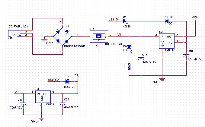
Is the power supply that i am using correct. This power supply should give me 3.3V and 5V and i am sure it does that. what i have always wondered was how to calculate the capacitor values at input and output of the regulator.
Can anyone put some light on this. 470uF at the input and 47uF at the output. I have also tried with 1000uF at input ant 100nF at output. Output is not a problem but the question really is how do i calculate the values.
I know input capacitor is a filter and output cap is for coupling but what about exact values. How to calculate them.