darcyrandall2004
Full Member level 1
- Joined
- Feb 1, 2009
- Messages
- 97
- Helped
- 3
- Reputation
- 6
- Reaction score
- 0
- Trophy points
- 1,286
- Location
- Perth, WA, Australia
- Activity points
- 2,099
Hello,
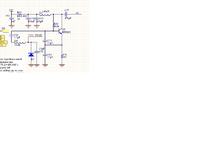
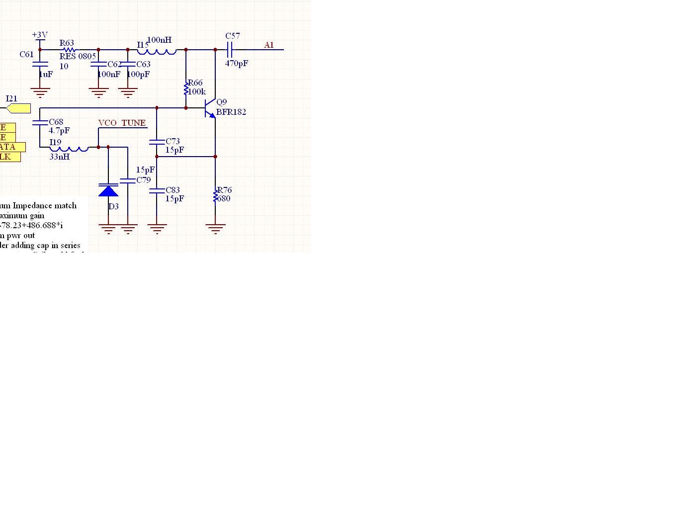
I am having difficulty with the VCO I have designed.
The VCO oscillates at the same frequency predicted by simulations but there is a whopping 30dbm less power available.
I have tried different impedance matching techniques to the output. I have tried increasing the bias current with still little output power.
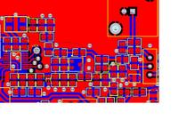
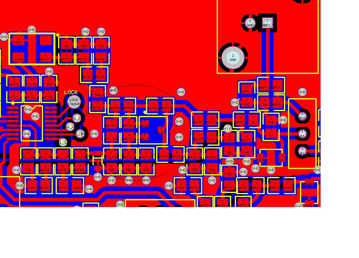
The board consists of 1.6mm FR4 with 35um copper traces. This is what I simulated in momentum. I did assume a perfect ground plane on the bottom of the board when in reality in some places it is broken by other traces.
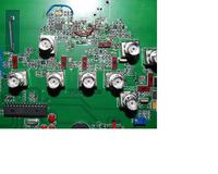
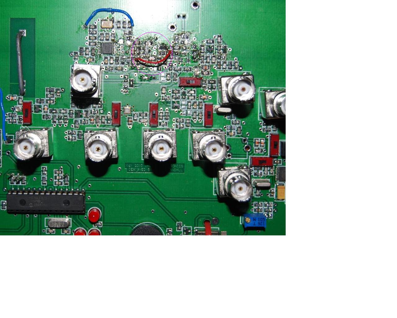
The picture below shows the actual board covered with BNC connectors for testing.
Does anyone have any ideas as to what the cause is or what I should try to get this working?
I think it is worth mentioning that I altered the circuit to bypass the BNC connector I was measuring from yet I was still picking up the signal. ie I guess not all power was being delivered to the desired load.
I am using BFR182 transistors. The linear and non linear models were available in ADS
Thankyou
I am having difficulty with the VCO I have designed.
The VCO oscillates at the same frequency predicted by simulations but there is a whopping 30dbm less power available.
I have tried different impedance matching techniques to the output. I have tried increasing the bias current with still little output power.
The board consists of 1.6mm FR4 with 35um copper traces. This is what I simulated in momentum. I did assume a perfect ground plane on the bottom of the board when in reality in some places it is broken by other traces.
The picture below shows the actual board covered with BNC connectors for testing.
Does anyone have any ideas as to what the cause is or what I should try to get this working?
I think it is worth mentioning that I altered the circuit to bypass the BNC connector I was measuring from yet I was still picking up the signal. ie I guess not all power was being delivered to the desired load.
I am using BFR182 transistors. The linear and non linear models were available in ADS
Thankyou