Welcome to our site! EDAboard.com is an international Electronics Discussion Forum focused on EDA software, circuits, schematics, books, theory, papers, asic, pld, 8051, DSP, Network, RF, Analog Design, PCB, Service Manuals... and a whole lot more! To participate you need to register. Registration is free. Click here to register now.
Afaik this display is 3.3V only? So most probably you'll blow it @ 5V
Here's a comparable project with PIC16F628 and Nokia 3310.
Schematic and Board in Eagle are also provided. Take a look at it: https://www.mikrocontroller.net/attachment/3464/Minniterminal.zip
why you are using 5 volts supply to the lcd ,layman knows in a cell phone max voltage inside cell phone is 4.2 volts when fully charged and this is regulated to circuit board lcd uses 3.3 v
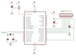
i have searched this code in the net,, can you please make a schematic out of this PIC BASIC pro program,using 16f877 and nokia 3310,,,
' This program uses the */ operator to scale the ADC result from 0-1023
' to 0-500. The */ performs a divide by 256 automatically, allowing math
' which would normally exceed the limit of a word variable.
' Connect analog input to channel-0 (RA0)
' Define LOADER_USED to allow use of the boot loader.
' This will not affect normal program operation.
Define LOADER_USED 1
' Define LCD registers and bits
Define LCD_DREG PORTD
Define LCD_DBIT 4
Define LCD_RSREG PORTE
Define LCD_RSBIT 0
Define LCD_EREG PORTE
Define LCD_EBIT 1
' Define ADCIN parameters
Define ADC_BITS 10 ' Set number of bits in result
Define ADC_CLOCK 3 ' Set clock source (3=rc)
Define ADC_SAMPLEUS 50 ' Set sampling time in uS
adval Var Word ' Create adval to store result
TRISA = %11111111 ' Set PORTA to all input
ADCON1 = %10000010 ' Set PORTA analog and right justify result
Low PORTE.2 ' LCD R/W line low (W)
Pause 500 ' Wait .5 second
This site uses cookies to help personalise content, tailor your experience and to keep you logged in if you register.
By continuing to use this site, you are consenting to our use of cookies.