Continue to Site

Welcome to EDAboard.com

Welcome to our site! EDAboard.com is an international Electronics Discussion Forum focused on EDA software, circuits, schematics, books, theory, papers, asic, pld, 8051, DSP, Network, RF, Analog Design, PCB, Service Manuals... and a whole lot more! To participate you need to register. Registration is free. Click here to register now.

Square Wave to Sine Wave Conversion Problem

Status
Not open for further replies.

asabalon

Junior Member level 1
Joined
Jun 24, 2010
Messages
15
Helped
0
Reputation
0
Reaction score
0
Trophy points
1,281
Location
Philippines
Activity points
1,380
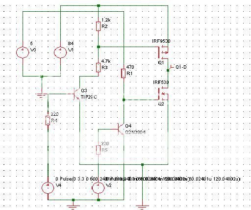
I made a motor driver which outputs an 84V, 2.5A varying frequency square wave. i wanted to convert it into a sine wave with almost the same parameters as my square wave. what type of circuit or filter must i use to be able to convert it properly? the figure below is my motor driver. V4 and V2 are 3.3V square wave and the output of my driver is between the two MOSFETs.
half-bridgephasea.jpg
 

i forgot to tell that my square wave's frequency is varying. from 5khz to 10kHz..is it possible for just an RC filter?
 

is it possible for just an RC filter
A higher order filter with about 12 kHz cutoff frequency could basically do. I don't understand, what you want to suggest with the driver circuit, however. To drive a motor with a sine wave, you either need a PWM modulator, a linear output stage, or an (almost) lossless LC filter between the square wave output stage and the motor. A RC filter can't help.

The controlling waveform for a PWM output stage or a sine waveform to drive a linear output stage can be better generated in the digital domain instead of using analog filters, if a microcontroller is available in your system.
 

i used a butterworth pi lc filter with 3 poles but it seems that my output sine wave is very small compared to my square wave. why is this happenning sir?
 

As any passive filter, it has to be matched to the load and source impedance. Apparently, it's not matched correctly. The source impedance of a saturated push-pull output stage is about zero, but what's the load in your test? Your circuit doesn't show a load at all.

You should tell the filter LC and load R values for clarity.
 

i'm using this circuit as a motor driver for Adept Cobra i600. i am not exactly sure what the impedance of the adept cobra i600 motors are so i wasn't able to put a load on my circuit. the filter i used was butterworth pi low pass filter with 3 poles. the values i used are listed below.

L1 7957.749 uH
C1 1591549.76 pF
C2 1591549.76 pF

my square wave input varies from 5khz to 10khz. i was thinking of using PWM. so i just want my filter to be fixed..
 

I see, that your filter has a cutoff frequency of 2 kHz and is matched for 50 ohm source and load impedance. Obviously, this is incorrect in any regard. (Seems like you used a filter tool with default 50 ohm impedance and missed the difference between Hertz and rad/sec...)

I also forgot to mention, that a pi filter can't work with zero source impedance.

I don't know anything about the of drives involved with Cobra i600 and can't help you with determining it's impedance. You may want to mention at least the motor type.

No motor has a pure real impedance, however, it's most likely inductive. Saying that a 12 kHz low-pass could solve the problem doesn't mean it's actually a good idea to use a cut-off frequency only slightly above the intended output frequency. At least an exact filter dimensioning is required then, impossible without exact knowledge of the load impedance (and a better understanding of basic filter theory).
 

The motors used for the Cobra i600 are four three-phase servo motors. The product name is Panasonic MSM motor. Sir what filter should i use to convert my square wave to a sine wave? I am not familiar with filters and I am just a beginner when it comes to circuit designing.
 

Do you really need a sine wave for the motor? Why won't square waves do?
 

Panasonic offers VFD inverters for MSM servos. According to the manual, they are PWM inverters without sine filters, simply using the motor inductance to "filter" the current waveform, as most industrial VFDs do.
 

sir, i really have to convert it to a sine. what filter must i use to be able to convert the square wave properly?
 

A LC filter exactly adapted to the motor impedance, that has to be measured before.
 

If the motor impedance would be 10 ohm real (I doubt that it is, it's rather complex with a strong inductive component),
a T-filter 191 uH, 1.7 uF, 63.7 uH corespondends to a 12.5 kHz fc butterworth characteristic.
 

Status
Not open for further replies.

Part and Inventory Search

Welcome to EDABoard.com

Sponsor

Back
Top