Continue to Site

Welcome to EDAboard.com

Welcome to our site! EDAboard.com is an international Electronics Discussion Forum focused on EDA software, circuits, schematics, books, theory, papers, asic, pld, 8051, DSP, Network, RF, Analog Design, PCB, Service Manuals... and a whole lot more! To participate you need to register. Registration is free. Click here to register now.

Explanation of a current sensor circuit

Status
Not open for further replies.

marco0674

Newbie level 6
Joined
Apr 20, 2007
Messages
12
Helped
0
Reputation
0
Reaction score
0
Trophy points
1,281
Activity points
1,372
Current sensor

Hi all.
Please take a look at this circuit:

86_1277767921.jpg


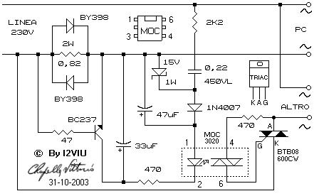
It is a "current sensor" circuit. When the PC is getting current the circuit turns on any other device connected to the triac.
What I don't understand is the reason of that 0.82Ω, 2W resistor in parallel with the two BY398 diodes.
Is it not enough to have those diodes in order to turn on the transistor?
Please let me know the theory behind all this: I'm getting crazy.

Thank you so much.

Marco
 

Current sensor

The 0.82ohm resistor turns on the transistor BC237 when the current is too high (i.e. R*I>0.8V or so), The two diodes BY398 protect the transistor BC237, should the current become really high.
 

Re: Current sensor

Sorry,
I continue to not understand.
If i have those 2 diodes, when current flows through them, I have a 0.7V that's enough to trigger the transistor, right? Those diodes are 3A, so no problem about current, that is less than 1A.
 

Re: Current sensor

For me this circuit looks a little bit dodgy, as the forward voltage drop across the top BY398 diode may be to low to allow the transistor to be turned on ..
To provide protection and not to interfere with the transistor, I’d use two diodes each way, and perhaps increase the value of the base resistor from 47ohm to, say 470 ohm ..

IanP
:D
 

Re: Current sensor

i think it can be like this:

when the current starts to increase , even before the diodes turned on the tr base gets the voltage and starts conducting.

once it is in conduction , its base- emitter voltage is limited by the diode forward drop.

in the reverse its limited to maxm of -Vdiode.

would like to hear whether it is.

srizbf
28thjune2010
 

Re: Current sensor

I think the resistor is there to lower the voltage drop when the current level is low. when current is low, the diodes are off. lower votlage drop result less power loss
 

Status
Not open for further replies.

Part and Inventory Search

Welcome to EDABoard.com

Sponsor

Back
Top