Continue to Site

Welcome to EDAboard.com

Welcome to our site! EDAboard.com is an international Electronics Discussion Forum focused on EDA software, circuits, schematics, books, theory, papers, asic, pld, 8051, DSP, Network, RF, Analog Design, PCB, Service Manuals... and a whole lot more! To participate you need to register. Registration is free. Click here to register now.

Design of the Fluorescent Lamp Ballast circuit

Status
Not open for further replies.

omara007

Advanced Member level 4
Joined
Jan 6, 2003
Messages
1,237
Helped
50
Reputation
102
Reaction score
16
Trophy points
1,318
Location
Cairo/Egypt
Activity points
9,716
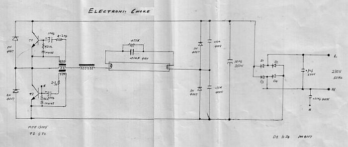
Does anyone have a full design of the Fluorescent Lamp Ballast circuit ? .. schematics with discrete components and their values are very welcome :) .. PCB layout is welcome as well .. :wink:
 

Re: Ballast Circuit

International Rectifier and ST Microelectronics have some ICs for electronic ballast. Look at their sites and you will find a lot of application circuits and useful informations.
 

Re: Ballast Circuit

Hi,
I don't know you are still interested or not, just post this file for you because I've lost the link to the original site. This is in Russian, but the schem is quite simple. If any question, just come back.
 

Re: Ballast Circuit

89_1156796941.jpg
 

I made an electronic ballast recently with IR2153 and opto-triac/triac on-off switching with pic timer. When I use the circuit without the timer(off state) nothing happens as one would expect, but when I connect the timer(although it's in off state) it literally evaporated the copper from the triac to the rectifiers( with no load on the output). I'm currently out of ideas what to check, because I can't find the problem. Any help would be appreciated.
 

Attachments

  • timer.pdf
    21.8 KB · Views: 104
  • timerbrd.pdf
    1.7 MB · Views: 115

Status
Not open for further replies.

Part and Inventory Search

Welcome to EDABoard.com

Sponsor

Back
Top