Continue to Site

Welcome to EDAboard.com

Welcome to our site! EDAboard.com is an international Electronics Discussion Forum focused on EDA software, circuits, schematics, books, theory, papers, asic, pld, 8051, DSP, Network, RF, Analog Design, PCB, Service Manuals... and a whole lot more! To participate you need to register. Registration is free. Click here to register now.

1/2 wire lcd and keyboard driver

Status
Not open for further replies.

joy123

Member level 2
Joined
Mar 19, 2010
Messages
44
Helped
1
Reputation
2
Reaction score
0
Trophy points
1,286
Activity points
1,589
hello,

just wondering if anybody has a good idea for my project, which is a buglar alarm, i am using LCD 16x2 display(10 wire), and 4x4 keyboard(8 wire). so i need 18 cable to connect the lcd and keyboard (which is beside the main door) to the main control box(beside the fuse box).

my house is pre-wired for alarm, there is a 6 core cable out beside the main door where i am planning to mount the keyboaard and display, so is there any idea how can i make this 18 cable to 6 cable out?


thanks in advance
 

one suggestion is to use I2C peripherals for keyboard and lcd controllers.

philips have such devices.

srizbf
9thjune2010
 

    joy123

    Points: 2
    Helpful Answer Positive Rating
also you could use shift registers, I don't recommend I2C because the lenght of the cable (bet it's larger than 5 meters)

but... where are you planning to set all the control logic? maybe you could put an small microcontroller for LCD display and keypad reading, and just communicate with the main controller with 3 pins (RS232 TXD,RXD & GS) and 2 pins for power! so sending/recienvig data will be easier... just search for "small terminal" or "microcontroller terminal with LCD Keypad" these just put on screen wathever they recieve and send any key you pressed.. of course you could do one to suit your needs...
 

    joy123

    Points: 2
    Helpful Answer Positive Rating
they are really some good idea, even tho i am not really famillier with 12c or shift registers, but think i have to look around to check if i can find some good project. if ye guys see any good one will you share the links,

@Kurenai_ryu its not larger than 5 meters, but i love to have this option incase i have to change the setup. all the control logic is setup and made already in the main control box for the alarm. which have total 18 pinout between lcd and keypad, i like your idea, if you have any example will you share with me?


    joy123

    Points: 2
    Helpful Answer Positive Rating
cool! this is looks easier, https://www.qsl.net/yo5ofh/pic/lcd_terminal/lcd_terminal.htm ,
one question tho, do i need to make 2 of them to connect to each other by RS232, one of them will be connect to alarm control board, and another one lcd+keypad. and do i have to change anything in the sorce file except lcd display type and keyboard type?
 

Just dont do what I did. Last time I programmed a keypad, I used a resister matrix and the uc's ADC to read keypresses. Only advantage was that it used a single I/O for 20+ keys and no additional logic chips.

Thing was a pain in the a** to calibrate.
 

    joy123

    Points: 2
    Helpful Answer Positive Rating
joy123, you must build just one! the one on front of the door (trough your 6pin available cable.)! BUT you must change the source file of your main controller so it doesn't write to the LCD. instead, it writes to a serial port (with a MAX232 will be rs232 ready for the terminal) and the main controller doesn't read a keypad, instead it reads a serial port (trough the same MAX232)... if you have the source code, and a free serial port (mostly any microcontroller will have one) it's a piece of cake...


about a single pin keypad... yes it's very difficult... i posted a solution on this page... it worked very well on Lab.
but take the tip from wassabi, it's the royal pain! also, the keypad can't be too long from the ADC input... it will degrade the voltage and catch some noise...
 

    joy123

    Points: 2
    Helpful Answer Positive Rating
i build my intrudure alarm which was published in EPE MAGAZIN april 2002 i have everything softcopy, its have pic16F877 and i have a sorce file too but it doesn't have any rs232. it might be easier to you but wont be easier for me :( 
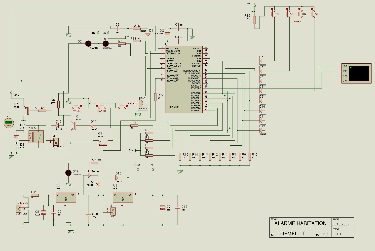
unless you wanna have a look?? i attached everything below.
 

huh! seems a very robust project... have you already builded it? does it works well?, i'm not very sure what or how does the seccond keypad works... (does it work the same way the first keypad?) lucky REPLACING the first keypad opens the RC6 and RC7 which are the PICs USART PORT (with a max232 and an appropiated Crystal value will have a working rs232)


so... it's possible, I'll look over my spare time, and hope if some one else can help us with this issue (migrating from keypad-lcd to usart)
 

    joy123

    Points: 2
    Helpful Answer Positive Rating
ya i built it already, i am not using the 2nd keypad. 2nd keypad optional, with limited functinality (only disarm and arm) i think. i didn't wire it up yet. its on the bench test for last 1 week, so far very good, no problem.

thanks, please do when you get chance.
 

still waiting, dont want to be lost.
 

mmm... sorry I'm busy right now... i have a project presentation at thusday and i'm working on it.... after thurday i'll have more free time (enough time to test the actual code, and make the right changes on it)... by the time try looking for serial communication on assembler over a PIC16f with USART... learn how it works...

also! which assembler program (or version) does this code works?? i tried MPASM and couldn't assemble it right out the box!!! (i you have the hex, it will help me to compare the one I got modificating the code for MPASM, please post it...)
 

    joy123

    Points: 2
    Helpful Answer Positive Rating
Kurenai_ryu said:
mmm... sorry I'm busy right now... i have a project presentation at thusday and i'm working on it.... after thurday i'll have more free time (enough time to test the actual code, and make the right changes on it)... by the time try looking for serial communication on assembler over a PIC16f with USART... learn how it works...

also! which assembler program (or version) does this code works?? i tried MPASM and couldn't assemble it right out the box!!! (i you have the hex, it will help me to compare the one I got modificating the code for MPASM, please post it...)
Hey, i m sorry i didn't mean to push u to do that. U r very kind. I dont know how to thank u. I will post the hax file in few min, after serching on net i found that it is a TASM stuff.., to be honest i m kinda confuse too. Anyway i have the hax file, which might help u.

Added after 1 hours 6 minutes:

here is all the file
 

ok, i got the files, i'm firstly... going to test (to see how it works) and then i'll suggest the changes needed to make it work with an rs232 terminal... I think it'll be easy.. but i'm a bit rusty at PIC assembler...
 

    joy123

    Points: 2
    Helpful Answer Positive Rating
thanks for helping me out, one other thing will you check?
in PASSIVE MODE, its works perfect when i have set all the channel for open contract, but if they set for close contract the buzzer always on. you will know what i mean.
 

mmmm... with the actual circuit.... what for is the small pic? (16f84) as you didn't attached it's code... anyway... i took it out an connected simple push-buttons to VCC... (those are normally open...) if you set to normally close you must also put at all the selected channels, normally closed buttons... (as far as i remember, there aren't any of those on proteus.. so have you tested with closed switches?)

I have modified the original code to assemble with MPLAB and got it without significant diferences...

so now the modifing part. I identified the LCDOUT procedure as the general output routine... i'll change it to some procedure to transmit data... the ONLY issue with this, is the diference between data byte and command byte... but as all is in english (so it uses 7-bit ASCII) and the only significant commands (in this program apart from initialization...) is the "goto" command which is command (0x80+position) (over 7 bit) we can send it without conflicts... (but must make a terminal which can interpret the 0x80 not as a character but as a command...)

for the keypad... I have detected 2 keypads procedures... i'm planning to replace both with a simple Recieve data... no fancy at all...

hopefully i'll get all ended by the weekend..
 

    joy123

    Points: 2
    Helpful Answer Positive Rating
sorry for late reply, i was away for weekend..
ya i forget to tell you to take away 16f84. i put 8 switch which could be normally open or normally close same in proteus dsn file i gave you, there is only 4( to change normally open or close you have to press the red dot beside the switch). and the original code works perfect as it should be except the PASSIVE MODE (.)
and i have it already assembled, with the original code and its for bench testing for last 2 weeks, no problem so far.

i am trying to change the passive mode to a all zone wathcing mode, and use it when nobody in home, and the alarm on mode for night time (so i can change the zone status) but i dont want you to be confuse so keep up your good works.


thanks again. if any other question let me know.
 

got a preliminary working! but i find very difficult to press 'D' (valid) and RESET the system... (at least i could press my last password ('1111' on the sim) and press '-'(blank) to get working...)

BUT this program NEEDs a 4MHz clock for working! i'm not sure about the 3.2MHz but I Think the SPBRG value must be changed from 25 dec to 20 dec... I didn't do this because the sim was at 4MHz... and got lasy to test it...

check, the keypad and the lcd are lost! use the virtual terminal to view data an d press character to send... (they are not visible, but they are sent anyway... just in case if you haven't used the virtual terminal before)


there are still many changes, like the exact position over the terminal LCD... maybe we should design our own terminal... it's not so difficult but must be compatible with all the circuit (with the lcd position, debouncing, waitkeypress, waitkeyprelease... etc.)

so now, you have power line, ground line, and a line for transmit to LCD and a line for recieving from keypad...

test it and comment about it...
 

    joy123

    Points: 2
    Helpful Answer Positive Rating
thats looks really good, thanks, i didn't try yet, i will try in 2 hr when i am home. is there any way i can use the keypad to check the board? i never use vartual port before.

ps: the red small button top of the valid key is for change the status of the key to alway close/open, i normally change the valid key always key first then, press the reset button once then change the valid key again to always open. just thought if its help you.

i will might come with more question soon!!!

Added after 1 hours 57 minutes:

ok, i found few things, like i cant stored the normally open/close at 6 and i cant put any value , but i can change the pin from 1. guess terminal part isn't finish yet!
 

Status
Not open for further replies.

Similar threads

Part and Inventory Search

Welcome to EDABoard.com

Sponsor

Back
Top