Continue to Site

Welcome to EDAboard.com

Welcome to our site! EDAboard.com is an international Electronics Discussion Forum focused on EDA software, circuits, schematics, books, theory, papers, asic, pld, 8051, DSP, Network, RF, Analog Design, PCB, Service Manuals... and a whole lot more! To participate you need to register. Registration is free. Click here to register now.

How to build a liner voltage regulator without opamp

Status
Not open for further replies.

jx_ben

Newbie level 5
Joined
Apr 22, 2010
Messages
8
Helped
0
Reputation
0
Reaction score
0
Trophy points
1,281
Location
auckland
Activity points
1,333
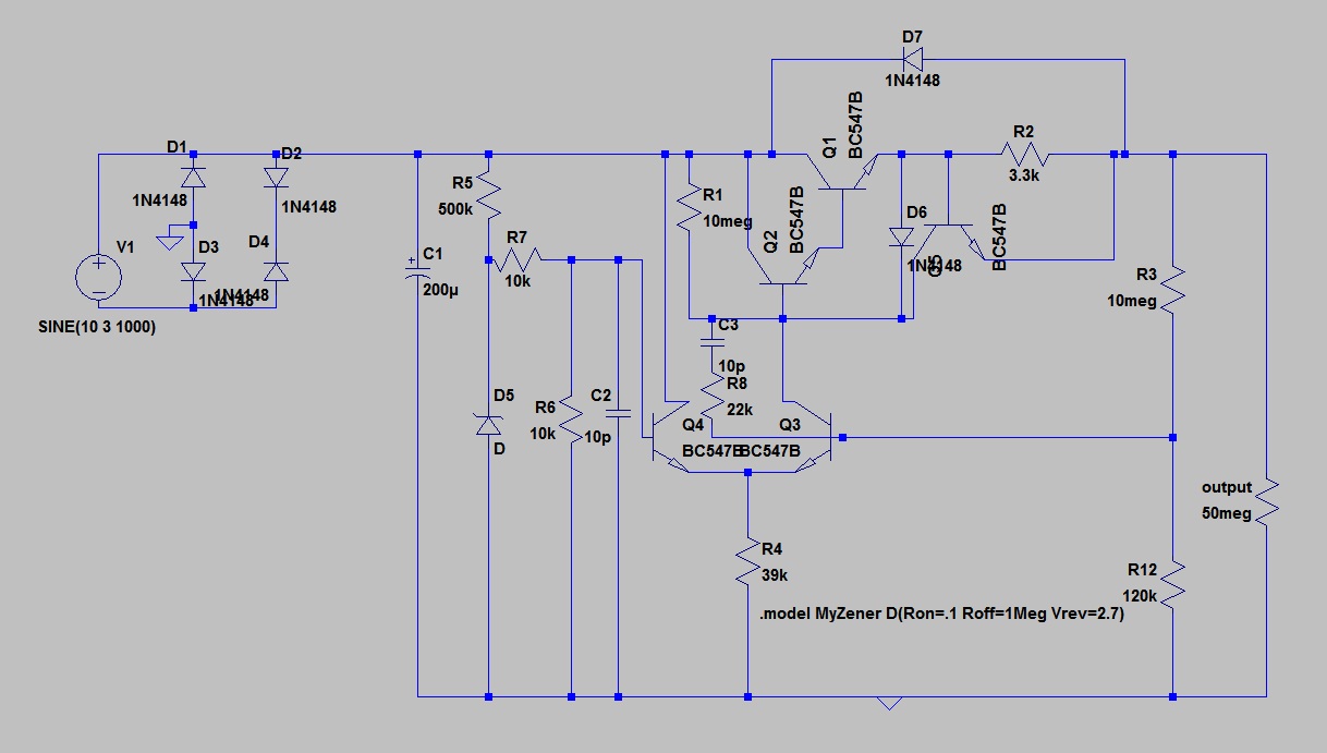
The project we are asked to deliver is to build a liner voltage regulator without opamp, only use transistors, diodes, and zener diodes. The input is a sine wave with peak values as 7 to 13v,and output is lower than 5v. how to build this regulator?
 

Yes, it is certainly possible. You may not get such good regulation due to the lower gain (depending on how many transistors you use). This is not what you want but might give you an idea. It is high voltage power supply I have designed and used before. The input is at the top left, the output top right. The voltage on Q5 base sets the output voltage based on the R2/R3 potential divider.

You could leave out Q3/R1 - they are for a current limit. R6/C2 is for compensation, for stability. I seem to remember it controlled around 300V from a low voltage on Q5 base (less than 5V).

Keith.
 

    jx_ben

    Points: 2
    Helpful Answer Positive Rating
If regulation is not a big issue you can design very simple voltage regulator based only on a few components such as Zener diode, NPN transistor and resistor .. see attached picture ..
Details and discussion is at:
https://www.ece.cmu.edu/~ee100/docs/Chapter5.pdf

Just keep in mind that the output voltage is roughly 0.65V lower than the Zener voltage; in other words, if the output voltage suppose to be 5Vdc the Zener diode should be rated for 5.6V ..

Rgds,
IanP
:D
 

A lot simpler than mine! It can be useful to have a minimum load on that sort of design at all times to improve the regulation. A bit wasteful, though. I guess another idea is a simple zener shunt and dropper resistor, but then it is wasteful of power.

Keith.
 

Q1, Q2, Q4 and Q 5 works like a very simple opamp where base on Q4 represent negative input and base on Q5 positive input.
 

Well, Q4/Q5 are a long tailed pair. Q1/Q2 form a darlington transistor. I think to say it is an opamp is a bit of an exaggeration :)

Keith.
 

keith1200rs said:
Well, Q4/Q5 are a long tailed pair.
Ok. I didn't know that connections name. Thanks

keith1200rs said:
Q1/Q2 form a darlington transistor.
Simple facts, yes it's pretty common, so I knew that :wink: [/quote]

keith1200rs said:
I think to say it is an opamp is a bit of an exaggeration :)
What did you eat this morning? I really never stated "it is an opamp".
 

If you look at some of the old National regulators like LM317,
there is no "op amp" per se; the bandgap gain loop encompasses
the output (through a divider) to close against the reference.
 

keith1200rs said:
Yes, it is certainly possible. You may not get such good regulation due to the lower gain (depending on how many transistors you use). This is not what you want but might give you an idea. It is high voltage power supply I have designed and used before. The input is at the top left, the output top right. The voltage on Q5 base sets the output voltage based on the R2/R3 potential divider.

You could leave out Q3/R1 - they are for a current limit. R6/C2 is for compensation, for stability. I seem to remember it controlled around 300V from a low voltage on Q5 base (less than 5V).

Keith.

hi Keith,
Thanks a lot, it really helped. But during simulating, even the source is produce 13v, and the circuit since not working. Is that because we were asked to use BC547B for transistor and 1N4148 for diode?
Ben
 

Don't copy my circuit values - it was designed for 300V so some of the resistor values are pretty high. You will need to reduce the resistor values quite a bit. Mind you, your bridge rectifier looks wrong as well. Start with a DC source & sort out the rectifier when you have the circuit working.

Keith.
 

Status
Not open for further replies.

Similar threads

Part and Inventory Search

Welcome to EDABoard.com

Sponsor

Back
Top