Continue to Site

Welcome to EDAboard.com

Welcome to our site! EDAboard.com is an international Electronics Discussion Forum focused on EDA software, circuits, schematics, books, theory, papers, asic, pld, 8051, DSP, Network, RF, Analog Design, PCB, Service Manuals... and a whole lot more! To participate you need to register. Registration is free. Click here to register now.

Isolation in strip line couplers

Status
Not open for further replies.

chandregowda

Full Member level 4
Joined
Jul 7, 2008
Messages
212
Helped
14
Reputation
28
Reaction score
4
Trophy points
1,298
Location
Bengaluru/Bangalore, India
Activity points
2,564
hi,

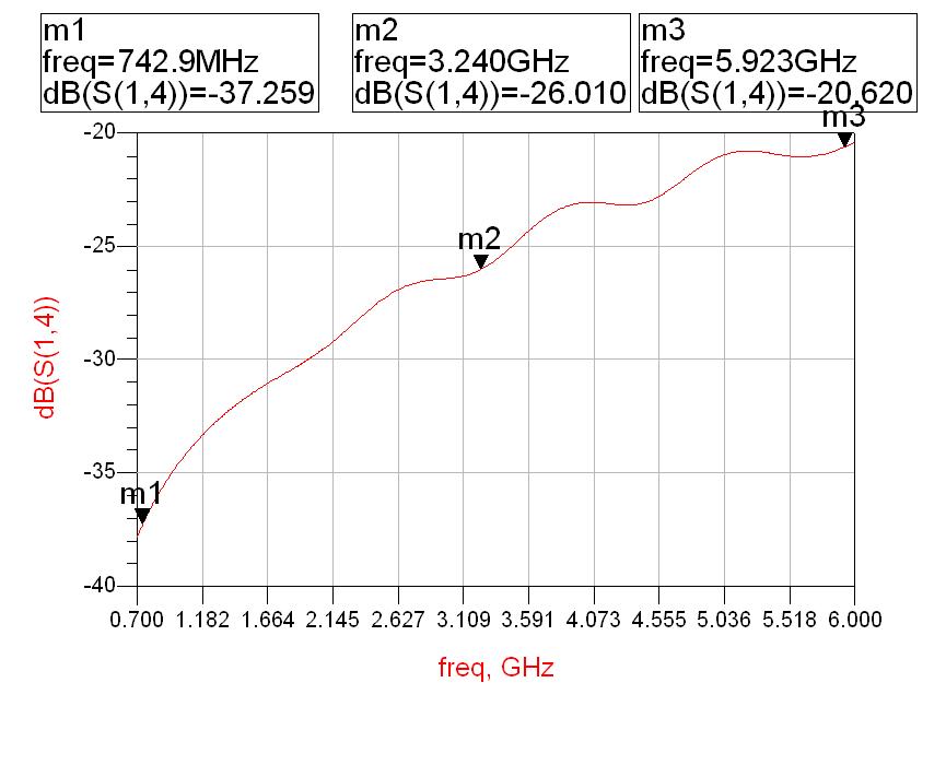
i have done wideband 15dB coupler upto 6GHz. the isolation S(1,4) is increasing curve from -37.83dB (@700MHz) to -20.5dB (@ 6GHz), the coupler was designed for 700-6000 MHz bandwidth. The other parameters return loss -24dB Min, insertion loss-0.6dB Max, coupling -15dB, flatness (± 0.8dB) of the coupler are ok.


how can we improve the isolation? if i calculate the directivity (isolation - Coupling) at 6GHz it will be 0dB or -0.5dB, is that oK?


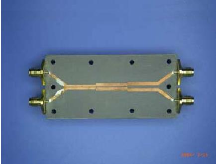
coupler is Strip line based design.


il is 0.6dB OK but flatness ± 0.8dB is confusing.
Also directivity at 6Ghz -20 minus -15 will be 5dB i do not know how u got 0dB
 

hi,

Flatness is 15±0.8dB in the overall frequency range from 700-6000MHz.
Directivity is 5dB @ 6000MHz not 0 dB, it was mistake that i have taken.


but a min of 10dB directivity is desirable, how do i improve that?


The design is Strip line edge coupling method.
 

Have you done the crossings?
like in telephones signal carrying conductors will be crossed to minimise the cross talk.
Better if you can share the design.
 

It's better to show your circuits.
Try to make the grounding better,especially the upper board.
 

hi,

it is basically Stripline technology with Edge coupling method
multi sections are used to get the broadband operation, sections are asymmetric.

width, W and separation between each section are calculated by even and odd mode impedances. W, S are optimized to get the proper coupling and other parameters.

but Isolation not met the specification, after varying these parameters.

100_1271920146.jpg
 

Current design has no symetry. it has closer or tight coupling on one side and loose coupling on the other.
change to lose-tight-again loose model.
 

hi,

thats right, we can go for symmetrical structure with loose-tight-loose coupling. how does it improves the isolation there and why not here in asymmetrical design?
 

Hello,

Can you please guide me on how to get the values for w and s for every section of the coupler?? Are there any calculators available for these?
 

Status
Not open for further replies.

Part and Inventory Search

Welcome to EDABoard.com

Sponsor

Back
Top