Continue to Site

Welcome to EDAboard.com

Welcome to our site! EDAboard.com is an international Electronics Discussion Forum focused on EDA software, circuits, schematics, books, theory, papers, asic, pld, 8051, DSP, Network, RF, Analog Design, PCB, Service Manuals... and a whole lot more! To participate you need to register. Registration is free. Click here to register now.

Simple code on LM35 + LCD operation, can be used?

Status
Not open for further replies.

delifadzli

Member level 2
Joined
Feb 5, 2010
Messages
50
Helped
0
Reputation
0
Reaction score
0
Trophy points
1,286
Location
malaysia
Activity points
1,774
here is sample source...that i have made using PCW C compiler...it about simple code on LM35 + LCD operation

this source explain about the temperature which being detect by LM35 display to LCD

here i wanna ask....isn't this code can be used?

since...when i compile ..there is no error.....


#include <16f877a.h>
#device ADC=10
#FUSES HS,NOWDT,NOPROTECT,NOLVP
#USE DELAY (CLOCK=20000000)

#include <stdio.h>
#include <math.h>
#include <stdlib.h>
#include <string.h>
#include <lcd.c>

//Define parameter

unsigned int temp_adc=0;
char L;
float temp;

void main()
{


set_tris_D(0x00); // Config PORTD for LCD display.

setup_adc_ports(AN0);
setup_adc(ADC_CLOCK_INTERNAL); // All channels are config as analog I/p.

lcd_init();

printf (L, "Temperature is:");
//procedure ADC

while(1)
{

temp_adc=read_adc();

temp= 5*temp_adc*(100.00/1023.00);


lcd_gotoxy(1,1);
lcd_putc('\f');
printf(lcd_putc,"Temp is:%f",temp);


delay_ms(50);


}


}


i hope some respond...

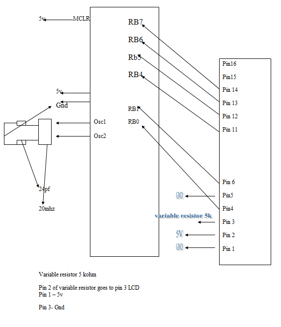
if there's no error, perhaps i will concentrating more on the hardware part
 

just to ask opinion

any respond?? please someone...

when i try to run it....the lcd doesn't show any result...

pin MCLr---connect to 5v

pin LM35- pin ANO

for lcd

pin 1- Gnd
pin2- 5 v
pin 3- variable resistor 470 k
pin 4- RD0
pin 5- gnd
pin 6-RD1
pin 11- RD4
pin12-RD5
Pin13-RD6
Pin14-RD7
Pin15-5 v
pin16-Gnd

pin 13-osc1--directly goes to oscillator 10mhz


please help..me...i'm new in programing..please
 

Re: just to ask opinion

use proteus and simulate your code and hardware on that.if still no response then tell me
 

just to ask opinion

I notice you are using 470K for contrast, this is way to high, about 10k is right. I think pin 3 can be shorted to ground for full contrast, you may not need the pot. If you use the appropriate flexlcd driver on the CCS forum, you can configure the pins you would like to use.
 

Re: just to ask opinion

#USE DELAY (CLOCK=20000000)
coding says that you are using 20mHz crystal and in the below line you are using 10mHz crystal.This would be the problem.
pin 13-osc1--directly goes to oscillator 10mhz
Change your crystal in hardware section to 20mHz.Aslo add two capacitors (15/20 pF)on crystal's each pin and ground them.
Hope this will solve your problem.
 

just to ask opinion

thanks...for all response...i will make adjustment on what u have said....beside all this, isn't others code that been given above...in correct condition....hopefully it will works....thanks anyway

Added after 1 minutes:

what about pin 4 and 6 at LCD...for RS and E...isn't need to be mentioned in writing this code...?
 

Re: just to ask opinion

U can use FlexLcd driver for LCD.Its easy to use,I have attached the file,download it.All pins descriptions are given here,also u can change the pins whatever you want.
Best of Luck.
 

Attachments

  • flexlcd_1590.rar
    2.1 KB · Views: 98

just to ask opinion

here is sample code...just for testing the lcd purpose...

#include <16F877A.h>
#fuses HS, NOWDT, NOPROTECT, BROWNOUT, PUT, NOLVP
#use delay(clock = 20000000)

#define LCD_DATA4 PIN_B4
#define LCD_DATA5 PIN_B5
#define LCD_DATA6 PIN_B6
#define LCD_DATA7 PIN_B7

#define LCD_ENABLE_PIN PIN_B1
#define LCD_RS_PIN PIN_B0

#include <lcd.c>

void main()
{
lcd_init(); // Always call this first.

while(1)
{
lcd_gotoxy(1,1);
printf(lcd_putc,"totally give up");


}


and stilll...the lcd doesn't show anything

i'm using lcd 16x1
connection pin

pin1- gnd
pin2 - 5v
pin3- gnd
pin 4- pin b0
pin 5-gnd
pin 6- pin b1
pin 11- pin b4
pin 12- pin b5
pin 13- pin b6
pin 14- pin b7
pin 15- 330 ohm goes to 5v
pin 16- gnd

for ur info, my first pic16f877 chip just burn out...it because of my voltage regulator(without heat-sink)...

please help...me...hopefully can someone provide diagram....
 

just to ask opinion

any response....

i just want a guidance...please....i totally dunno what to do....i have try all the step by reading other topic in this forum.....still no result..?

i'm using 20 mhz crystall clock..

and sometimes i try to implement 5k pot at pin3 of lcd..still no result...huhu...
 

Re: just to ask opinion

Upload your complete schemtic (if possible) so we can see is there any hardware problem or not.
 

just to ask opinion

ok...here is sample diagram...*sorry my software for schematic diagram corrupted ( i don't why)...maybe virus....so... i redraw it again...sorry....


Re: just to ask opinion

Which driver file you are using for LCD.
Upload your lcd.c file
 

just to ask opinion

#include <16F877A.h>
#fuses HS, NOWDT, NOPROTECT, BROWNOUT, PUT, NOLVP
#use delay(clock = 20000000)

#define LCD_DATA4 PIN_B4
#define LCD_DATA5 PIN_B5
#define LCD_DATA6 PIN_B6
#define LCD_DATA7 PIN_B7

#define LCD_ENABLE_PIN PIN_B1
#define LCD_RS_PIN PIN_B0

#include <lcd.c>

void main()
{
lcd_init(); // Always call this first.

while(1)
{
lcd_gotoxy(1,1);
printf(lcd_putc,"totally give up");


}

this is the overall coding...driver file?? can u explain about it...i'm still new in programming....

but in this source code i had include lcd.c...is still not enough??....can u explain a litle bit...sorry for my weakness...
 

Re: just to ask opinion

Just try the following code and in the line where you are including Flexlcd2.c give the complete location.I have also attached the Flexlcd2.c driver

Code:
#include <16F877A.H> 
#fuses HS,NOWDT, NOPROTECT, PUT, NOLVP 
#use delay(clock = 20000000)
#use rs232(baud=4800,xmit=PIN_C6,rcv=PIN_C7,parity=N,bits=8,stop=1)
#include <string.h>
#include <stdlib.h>
#include <your location where you save lcd driver file \Flexlcd2.c>


void main()
{
 lcd_init();//LCD should be initialize at start.
 delay_ms(10);
 while(1)
 {
  lcd_gotoxy(1,1);
  printf(lcd_putc,"\fHello");
  delay_ms(500);
 }
}

Hope this will solve your problem.
 

just to ask opinion

thanks for the help...i will try to implement it...so, by using flexlcd...i can connect the pin at any pin of pic16f877a.....
 

Re: just to ask opinion

Yes you can, just change the pin designations in the driver and whether to use 6 or 7 pins. Its documented within the driver file. You can even split pins across ports if you wish. There are a few diffent variations of this file, for 1,2 or 4 lines I think. Make sure you get the correct one for the display you are using.

Added after 7 minutes:

// Flex_lcd_16x1.c This is the variant for single line, electrically configured as 8x2

// These are randomly assigned pins, used to test
// that the driver can work with any arrangement
// of i/o pins.

#define LCD_RS PIN_D7
#define LCD_E PIN_B1
#define LCD_DB4 PIN_B2
#define LCD_DB5 PIN_B3
#define LCD_DB6 PIN_B4
#define LCD_DB7 PIN_B5
//#define LCD_RW PIN_B6 // enable this if you are using R/W (7 Wires)

// If you want to use a 6-pin interface for your LCD, then
// connect the R/W pin on the LCD to ground and comment
// out the following line. A 6-pin interface to the LCD
// is used if only have a few free i/o pins available on
// your PIC, and you want to use the smallest possible
// number of pins for the LCD.

//#define USE_LCD_RW 1

//========================================
// Use "2 lines" as the lcd type for the 16x1 LCD.
// The LCD is the same as an 8x2 LCD, but with the
// bottom line appended on the right side of the first line.
#define LCD_TYPE 2 // 0=5x7, 1=5x10, 2=2 lines
#define LCD_2ND_HALF_ADDRESS 0x40 //change back to 0x40 for hardware 0x88 = test (proteus)

#define LCD_WIDTH 16
#define LCD_HALF_WIDTH (LCD_WIDTH/2)

int8 const LCD_INIT_STRING[4] =
{
0x20 | (LCD_TYPE << 2), // Func set: 4-bit, 2 lines, 5x8 dots
0xc, // Display on
1, // Clear display
6 // Increment cursor
};

int8 lcd_xcoord;


//-------------------------------------
void lcd_send_nibble(int8 nibble)
{
// Note: !! converts an integer expression
// to a boolean (1 or 0).
output_bit(LCD_DB4, !!(nibble & 1));
output_bit(LCD_DB5, !!(nibble & 2));
output_bit(LCD_DB6, !!(nibble & 4));
output_bit(LCD_DB7, !!(nibble & 8));

delay_cycles(1);
output_high(LCD_E);
delay_us(2);
output_low(LCD_E);
}

//-----------------------------------
// This sub-routine is only called by lcd_read_byte().
// It's not a stand-alone routine. For example, the
// R/W signal is set high by lcd_read_byte() before
// this routine is called.

#ifdef USE_LCD_RW
int8 lcd_read_nibble(void)
{
int8 retval;
// Create bit variables so that we can easily set
// individual bits in the retval variable.
#bit retval_0 = retval.0
#bit retval_1 = retval.1
#bit retval_2 = retval.2
#bit retval_3 = retval.3

retval = 0;

output_high(LCD_E);
delay_us(1);

retval_0 = input(LCD_DB4);
retval_1 = input(LCD_DB5);
retval_2 = input(LCD_DB6);
retval_3 = input(LCD_DB7);

output_low(LCD_E);
delay_us(1);

return(retval);
}
#endif

//---------------------------------------
// Read a byte from the LCD and return it.

#ifdef USE_LCD_RW
int8 lcd_read_byte(void)
{
int8 low;
int8 high;

output_high(LCD_RW);
delay_cycles(1);

high = lcd_read_nibble();

low = lcd_read_nibble();

return((high << 4) | low);
}
#endif

//----------------------------------------
// Send a byte to the LCD.
void lcd_send_byte(int8 address, int8 n)
{
output_low(LCD_RS);

#ifdef USE_LCD_RW
while(bit_test(lcd_read_byte(), 7)) ;
#else
delay_us(60);
#endif

if(address)
output_high(LCD_RS);
else
output_low(LCD_RS);

delay_cycles(1);

#ifdef USE_LCD_RW
output_low(LCD_RW);
delay_cycles(1);
#endif

output_low(LCD_E);

lcd_send_nibble(n >> 4);
lcd_send_nibble(n & 0xf);
}

//----------------------------
void lcd_init(void)
{
int8 i;

output_low(LCD_RS);

#ifdef USE_LCD_RW
output_low(LCD_RW);
#endif

output_low(LCD_E);

// Some LCDs require 15 ms minimum delay after
// power-up. Others require 30 ms. I'm going
// to set it to 35 ms, so it should work with
// all of them.
delay_ms(35);

for(i=0 ;i < 3; i++)
{
lcd_send_nibble(0x03);
delay_ms(5);
}

lcd_send_nibble(0x02);

for(i=0; i < sizeof(LCD_INIT_STRING); i++)
{
lcd_send_byte(0, LCD_INIT_STRING);

// If the R/W signal is not used, then
// the busy bit can't be polled. One of
// the init commands takes longer than
// the hard-coded delay of 60 us, so in
// that case, lets just do a 5 ms delay
// after all four of them.
#ifndef USE_LCD_RW
delay_ms(5);
#endif
}

lcd_xcoord = 1;
}

//----------------------------
// The x-coordinate can be 1 to 16.
// The y coordinate is ignored.
// This x,y interface is kept in order to be
// consistent with other CCS LCD drivers.
void lcd_gotoxy(int8 x, int8 y)
{
int8 address;

// Update the global x-coordinate variable with the
// current x coordinate.
lcd_xcoord = x;

// Convert the x-coordinate from CCS format (1-16) to
// the 0-15 format used by the LCD hardware.
address = x - 1;

// If the x-coordinate is within the 2nd half of the
// LCD line, the address must be adjusted because
// of the special architecture of the 8x2 LCD.
if(address >= LCD_HALF_WIDTH)
{
address += (LCD_2ND_HALF_ADDRESS - LCD_HALF_WIDTH);
}

lcd_send_byte(0, 0x80 | address);
}


//-----------------------------
void lcd_putc(char c)
{
switch(c)
{
case '\f':
lcd_send_byte(0,1);
delay_ms(2);
lcd_xcoord = 1;
break;

case '\n':
lcd_gotoxy(1,1); // Goto start of line 1
break;

case '\b':
lcd_send_byte(0, 0x10);
lcd_xcoord--;
if(lcd_xcoord == LCD_HALF_WIDTH)
lcd_gotoxy(LCD_HALF_WIDTH, 1);
break;

default:
lcd_send_byte(1, c);
lcd_xcoord++;
if(lcd_xcoord == (LCD_HALF_WIDTH +1))
lcd_gotoxy(LCD_HALF_WIDTH +1, 1);
break;
}
}

//------------------------------
#ifdef USE_LCD_RW
char lcd_getc(int8 x, int8 y)
{
char value;

lcd_gotoxy(x,y);

// Wait until busy flag is low.
while(bit_test(lcd_read_byte(),7));

output_high(LCD_RS);
value = lcd_read_byte();
output_low(lcd_RS);

return(value);
}
#endif
 

just to ask opinion

it seems the driver ur given quite...long...isn't compulsory for me to understand all of this...if i'm using LCD 16x1 and not planning to change anything of the driver content...so...the connection will be like this?

#define LCD_RS PIN_D7
#define LCD_E PIN_B1
#define LCD_DB4 PIN_B2
#define LCD_DB5 PIN_B3
#define LCD_DB6 PIN_B4
#define LCD_DB7 PIN_B5

other just the same connection ? am i right?

Added after 1 minutes:

sorry - i'm actually new to this...perhaps..maybe some of the content of this driver can't be understand...
 

just to ask opinion

i wanna ask ....for the code given...

#use rs232(baud=4800,xmit=PIN_C6,rcv=PIN_C7,parity=N,bits=8,stop=1)

for the stop=1, what it stand for?....since when i try to compile it, it give an error...the compilation of the code is completed as the stop=1 been removed...

isn't ok..?...or still no result will exist...?

Added after 13 minutes:

plus...it the flexcd2 ur...given...why the contain is quite different which the latter lcd driver ur sent...?...do i need to replace all the code ( LCD 20x4) ur given to (LCD 16x1)...huhu??

Added after 23 minutes:

after i try u source code...and the connection given in lcd driver...

the lcd....produced result...but...not hello world just like ur state in ur code...but just...dot...dot...bar...code...


just to ask opinion

so,based from this link, you stated that the problem lies on source code?...still need adjustment?....

right know, i'm going to do a test...perhaps...tonight i will respond to ur about the result...hopefully u willing to help...
 

Status
Not open for further replies.

Similar threads

Part and Inventory Search

Welcome to EDABoard.com

Sponsor

Back
Top