gres
Full Member level 4
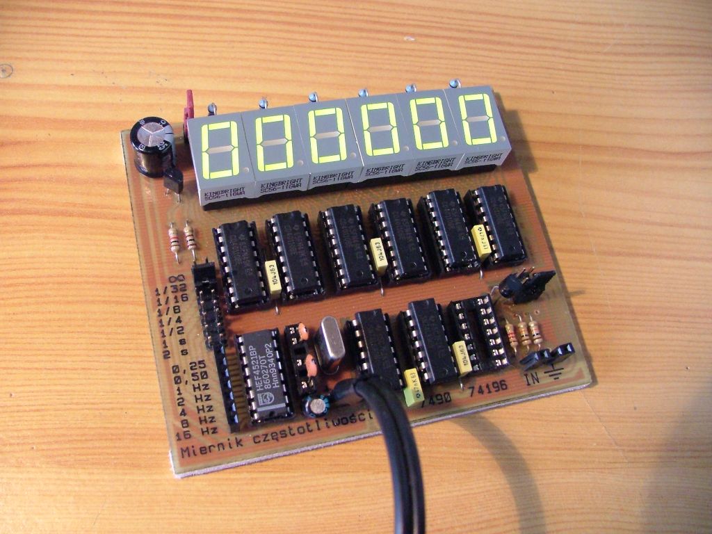
Everything should be as simple as it is possible, but not no-frills – Alert Einstein This was main idea for that project. Tool can be used as a frequency meter for ¼ Hz to 100MHz, impulse counter up to 100 000 000, also as a simple generator of square signal with frequency ¼ -16Hz.
Assumptions:
- to make nice tool based on TTL/CMOS before I start fight with microprocessors
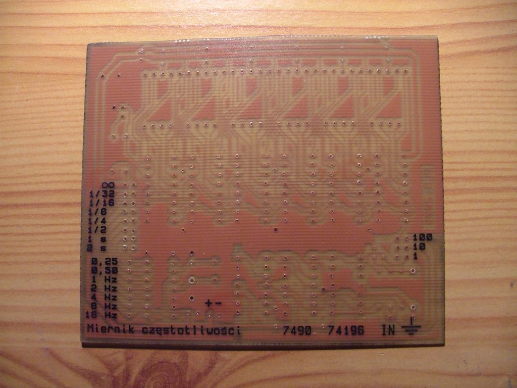
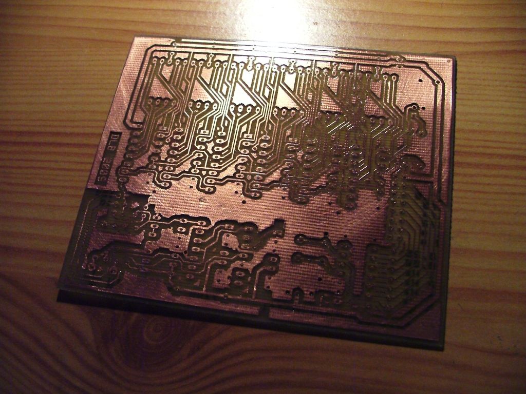
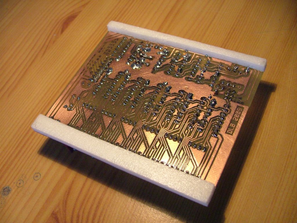
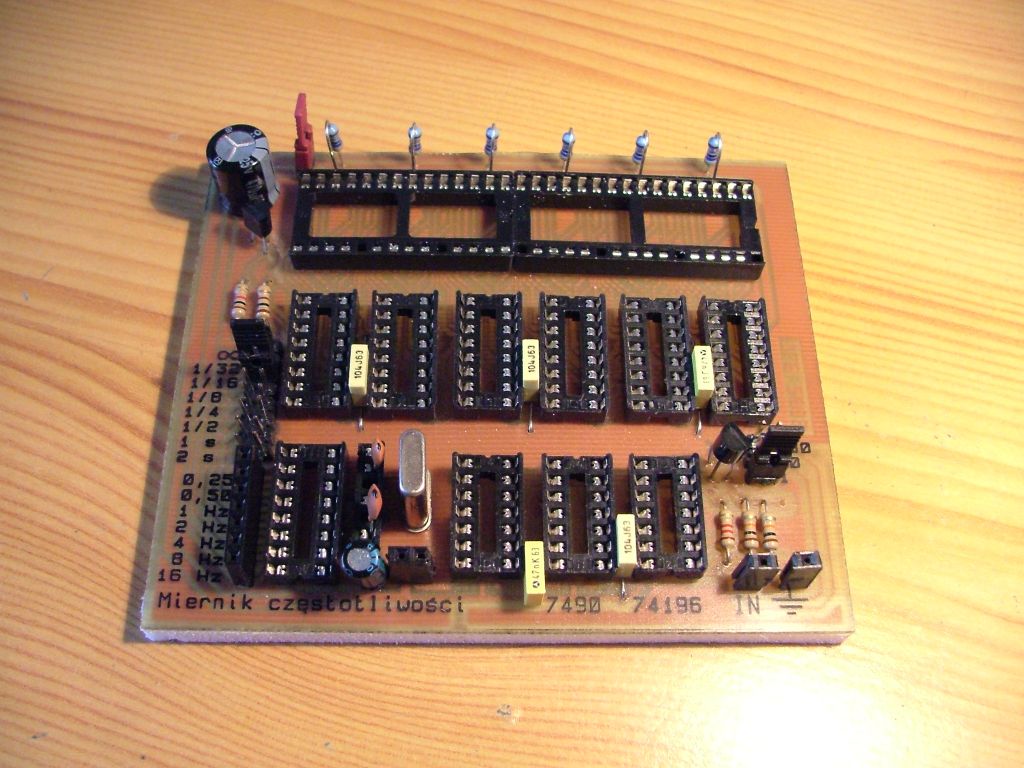
- to design one side board without any jumpers (300 of solder poles)
- to check if I can design a functional tool
Main idea:
Frequency is a number of impulses at one second period. So system must consist a counter and time standard. As a counter we have six 40110 systems in concatenation. Those counters are very polite- as they consist display driver . As a time standard we have 4521 with 4194304Hz quartz, that can gile ¼-16 Hz at outputs. This quartz frequency is the best as it is multiple number for 2 and you can easily division.
Counters are controlled by signal with 0,5 Hz. That means that through 1 second status is 1 and through next second is 0. this signal is gained by transistor T2 ant put into 12 inputs that control the counters. When counters got 0 they start to count, when 1 – result is displayed at the display through 1 second.
Signal is gained by simple input system with transistor and it goes to first counter, or is divided by 10 or 100. divisor can be choose by jumper.
Firstly you need to calibrate the system. You can do this by DIL stand with ceramic condenser. We get simple measuring instrument and built the simplest generator on NE555 so it can give about 1MHz. We connect both instruments and choose condenser to get the same result at both.
More information you can find at https://www.elektroda.pl/rtvforum/topic1586068.html
")