gres
Full Member level 4

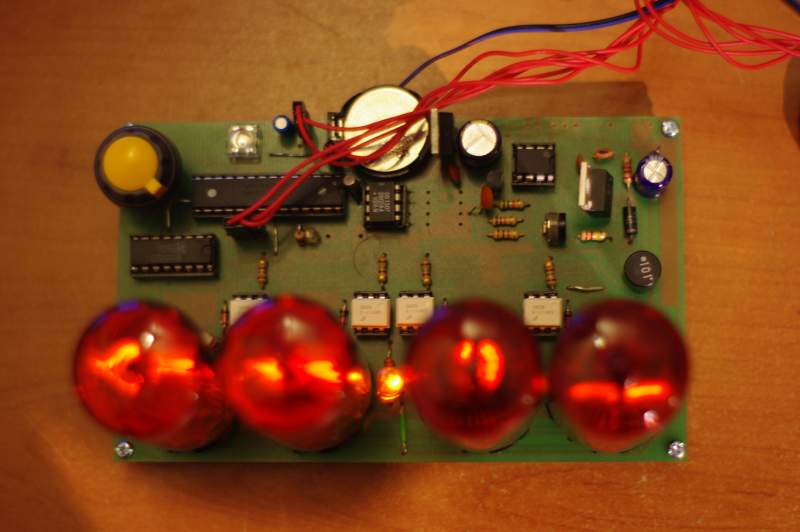
Clock consist 4 lamps with standard functions of showing time. It is set on board about 13x8cm. Power by single voltage 8-15V. with 12V it needs 350mA.
I put a few Unconventional solutions:
- pulse generator. This yellow ball at the back. It works really fine, one circle is 30 impulses, of course you need to make a lot of rotations but it’s retro style
- power bak up in case of no power. There is DS1307 system and CR2032 battery. It should work for long years. Works on TWI ( or I2C)
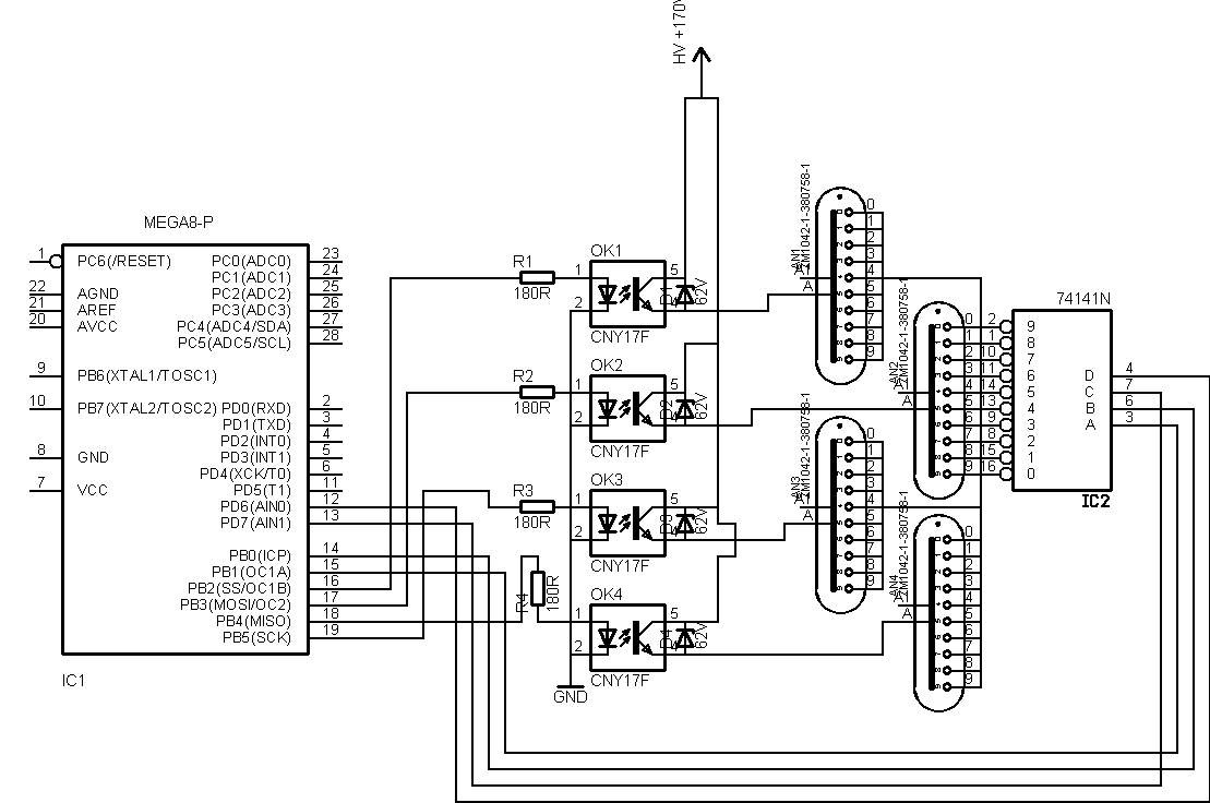
- most interesting. You can see it at the diagram. Most construction for anode controls works with pair of high voltages transistors or (rare) high voltages transoptors TLP. Often those elements are hard to buy. But I found that they aren’t necessary.
You need to look at the lamp in other way , not like at resistor. As we know it start to flash after got ignition. When voltage is lower it don’t conduct current ( just a little bit). So we can put voltage there, until we reach ignition – current want flow. Ok so to turn on/off the lump, we don’t have to plug 160-180V. Much less is also enough. Exactly we need difference between ignition voltage and filament voltage. Depend on rear side of the lamp it is difference, but 60V should be ok. And old good CNY17 can hold up to 70V between collector and emitter, and it works! But there is one problem. When transistor is stock, at the lamp is potential difference. In series connection with stock transoptor it couse that at pins voltage is more than 70V, and as I said it is enough to destroy CNY17. solution is very simple. We add an Zener diode 62V between C and E in transoptor.
That’s the way to exchange hard to buy elements like 2 resistors and 2 transistors, into transoptor, diode and resistor.
Original text at
https://www.elektroda.pl/rtvforum/topic1547559.html