Continue to Site

Welcome to EDAboard.com

Welcome to our site! EDAboard.com is an international Electronics Discussion Forum focused on EDA software, circuits, schematics, books, theory, papers, asic, pld, 8051, DSP, Network, RF, Analog Design, PCB, Service Manuals... and a whole lot more! To participate you need to register. Registration is free. Click here to register now.

Using PWM to control old analog gauge

Status
Not open for further replies.

edwinost

Newbie level 5
Joined
Mar 9, 2010
Messages
10
Helped
0
Reputation
0
Reaction score
0
Trophy points
1,281
Activity points
1,370
Hello,

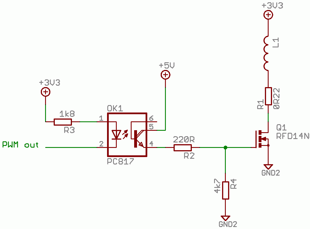
I'm trying to control an old analog gauge using an PWM output. The gauge I use has slightly odd ratings, for a 100% reading it needs 5 Amps at about 1,3 Volt (it comes from an 60 year old railway locomotive).

The three top connectors on the gauge are used for internal light. The bottom 2 connectors are for the actual gauge.

My first thoughts were to use a MOSFET to switch the current using a 3,3 Volt and 24 Amps powersource (old PC powersupply). Is this the best way to go or are there better solutions.

Below are 2 pictures of the gauge:

**broken link removed**

Regards Edwin
 

Does it have a separate shunt resistor internally? It is difficult to see from the picture. If so, removing that or increasing the value would make it easier to drive with less power.

Otherwise, what you suggest sounds along the right lines, although being a current meter it is the current you need to control rather than the voltage. Assuming the resistance is constant then voltage will work, but if the resistance changes as it heats up the reading will drift.

Keith.
 

Hi Keith,

as far as I can see there is no Shunt inside the gauge. It seems like the gauge does respond linear to voltage changes when feeded with 5 Amps. it doesn't really seems te get hot, the coil inside the gauge is rather large and massive. It's 60 years old build quality, build to last!

I am going to try the MOSFET approach. The schematic at the bottom of this tread: seems to be the setup i need as well, only instead of 12 Volt i feed with 3,3 Volts.
 

That's a 110A MOSFET which is a bit oversized for what you need. Also, it's threshold voltage can be as high as 4V so 3.3V won't turn it on.

You need a "logic level" FET. Depending on your PWM you might be able to get away with a simple MOSFET straight from the micro pin without a gate drive chip. Add a small resistor to limit the current into the gate. Something like the RFD14N05L might be a better choice.

Keith.
 

Hi Keith,

I have made diagram of the setup using your suggestion for a logic level mosfet. I'm not completely sure the diagram is correct, maybe I'm doing things that are impossible.
I like to use opto couples between my microcontroller and the mosfet but I don't know if the pwm signal and the optocoupler work well together.
Also I don't exactly know the risks of connecting the microcontroller directly to the mosfet and how to connect them then.

Regards,

Edwin
 

It is only worthwhile opto-isolating if the micro (PWM source) and high current power supplies are separate. It seems like they are (although I see +5V in your diagram - is that correct or is that really +3.3V?).

You have a drawing error in that you have grounded the end of the 33k - you need to remove the ground short.

One problem with that circuit is that it will not drive the gate as hard due to the drop in the optocoupler, but with 5V it will be fine. If you only hade 3.3V for the gate it would start to be a problem I think.

So, the changes I would suggest are:

1. make the 10k driving the PC817 a lot smaller - maybe 1.8k.

2. make the 33k to the gate a lot smaller - around 220 ohms

3. It is difficult to know what value resistor to put in the gate - ideally I would say if the meter wants 5A, I would suggest you design for something like 6A or 7A peak. Can you measure the meter resistance? If not, I would suggest you start off with 0.5 ohms for the resistor. You may find you cannot get maximum current, in which case you may need to reduce the value.

4. Add a resistor from the gate to ground. Maybe around 4.7k - otherwise the transistor will never turn off. Ideally that would be lower but to do that you need to reduce the 1.8k on the photodiode side but I don't know what current your PWM can drive. It can probably sink more than it can source, so it might be better to drive the cathode and connect the anode to +3.3V through the resistor.

Keith.
 

Hi Keith,

The sink/source current of my microcontroller is 40mA. It is a 5 Volt output.

I measured the resistance in the gauge, it is between 0,3Ω and 0,4Ω.

I have an unused computer powersupply which puts out both 5 and 3.3 Volts, so for that I want to use the same power source, just at different voltages. It is however completely separated from the microcontroller power source. I love optocouples cause I have the tendency to otherwise blow up the microcontroller every 2 hours :)

For the 0,5 Ohm resistor would a 15W version be sufficient?

I updated the design but I'm uncertain I did the grounding right this time.

Edit: I should have drawn the 220Ω resistor between the Gate and Ground. Also should the 0,5Ω Resister be on the Source (like in the drawing) or Drive side?

Regards,

Edwin
 

I have drawn out what I think you need.


I think the current limiting resistor will need to be less than 0.5 ohms. A 0.22 ohm will dissipate 5.5W at 5A average.

As you can drive 40mA from the PWM you could reduce the resistors quite a bit. Around 390 ohms for R3 will drive the LED with 5mA. Then maybe 82 ohms for R2 and 1.5k for R4.

The main benefit of reducing the resistors is faster switching which will reduce power dissipation. The MOSFET will dissipate very little power except when it is in transition. By speeding up the transition you reduce the losses.

I have drawn the PWM sinking current, mainly because chips usually sink more current (with lower voltage drop) but you couldl do either.

Keith.
 

    edwinost

    Points: 2
    Helpful Answer Positive Rating
Hi Keith,

I've ordered the parts for the circuit, I will report back how the solution works!

Thank you for the assistance.

Regards,

Edwin
 

The solution was a complete succes, the gauge works like a charm. I have made a YouTube video of it in action.

https://www.youtube.com/watch?v=3H2lsUiiWoU

Next on the list is controlling an similar gauge but instead of 3,3 volts and 5Amps it needs 200Volts and not so many amps. I was thinking about exchanging the Mosfet with a K4021 from Toshiba. It can handle 250 Volts and 4,5 Amps (should be more than enough).

The optocouplers I use (PC817's) can handle an Collector-Emitter voltage of 35V so do I understand it right that I can put 12V on the optocoupler output side to switch the mosfet?

Other question I have is this: The 200V Gauge has an internal resistance of 10,6kΩ. If looking at the diagram above do I need to alter the values of R1, R4 and R2? The +3,3V will become +230V. The +5V could become +12V because I have 12V available.

Regards,

Edwin
 

I am not sure why you are doing it, but I am pleased it works!

Yes, you can use 12V instead of 5V on the optocoupler.

What current does the 200V gauge need for a full scale reading or is it really a voltmeter? 200V/10.6k 19mA.

If you are using 12V instead of 5V I would increase R2 to maybe 180 ohms (assuming you used 82 ohms before).

The 2SK4021 looks fine - a bit bigger than you need. I would probably pick something with a higher Vds rating if you can - it will be less likely to blow up if you get an inductive/kickback. In fact, if the meter is inductive (and at 10.6k I am guessing it has a lot of turns) then you need a protection diode across the meter otherwise when you turn the transistor off the meter inductance will blow it up. Something like a UF4007 maybe.

Keith.
 

Hi Keith,

the gauges are going to be used in a railway locomotive simulator that I'm going to connect to a simulation game. The reason for the old gauges is that the locomotive i chose as example is a 60 year old German build electric locomotive. The gauges are original from a wreacked locomotive.

The gauge is internally quite different from the Amps meter, it has next to the wounding of the gauge itself 2 separate woundings and a big 2k7 resistor. I have an idea that the gauge coil is a far less voltage than the input. I tried bypassing the 2 coils and resistor, this gave me a linear readout from 0 to 12 Volts of the gauge. So I guess that the same circuit used for the Amps meter can also be used for this gauge. Except that I don't need a big resistor to tame all the Amps I think.

I measured the resistance in the gauge bypassing the resistor and 2 coils and it reads about 700 Ohms.

Regards,

Edwin
 

edwinost said:
Hi Keith,

The gauge is internally quite different from the Amps meter, it has next to the wounding of the gauge itself 2 separate woundings and a big 2k7 resistor. I have an idea that the gauge coil is a far less voltage than the input. I tried bypassing the 2 coils and resistor, this gave me a linear readout from 0 to 12 Volts of the gauge. So I guess that the same circuit used for the Amps meter can also be used for this gauge. Except that I don't need a big resistor to tame all the Amps I think.

Regards,

Edwin

Edwin,

Yes, it sounds like it is really a sensitive ammeter being used to measure voltage by adding a resistor. So, a lot easier to do - like the other meter.

Keith.
 

Status
Not open for further replies.

Part and Inventory Search

Welcome to EDABoard.com

Sponsor

Back
Top