Continue to Site

Welcome to EDAboard.com

Welcome to our site! EDAboard.com is an international Electronics Discussion Forum focused on EDA software, circuits, schematics, books, theory, papers, asic, pld, 8051, DSP, Network, RF, Analog Design, PCB, Service Manuals... and a whole lot more! To participate you need to register. Registration is free. Click here to register now.

electronic components in the PCB

Status
Not open for further replies.

flyerwolf

Newbie level 4
Joined
Dec 13, 2009
Messages
7
Helped
0
Reputation
0
Reaction score
0
Trophy points
1,281
Location
Nederland
Activity points
1,327
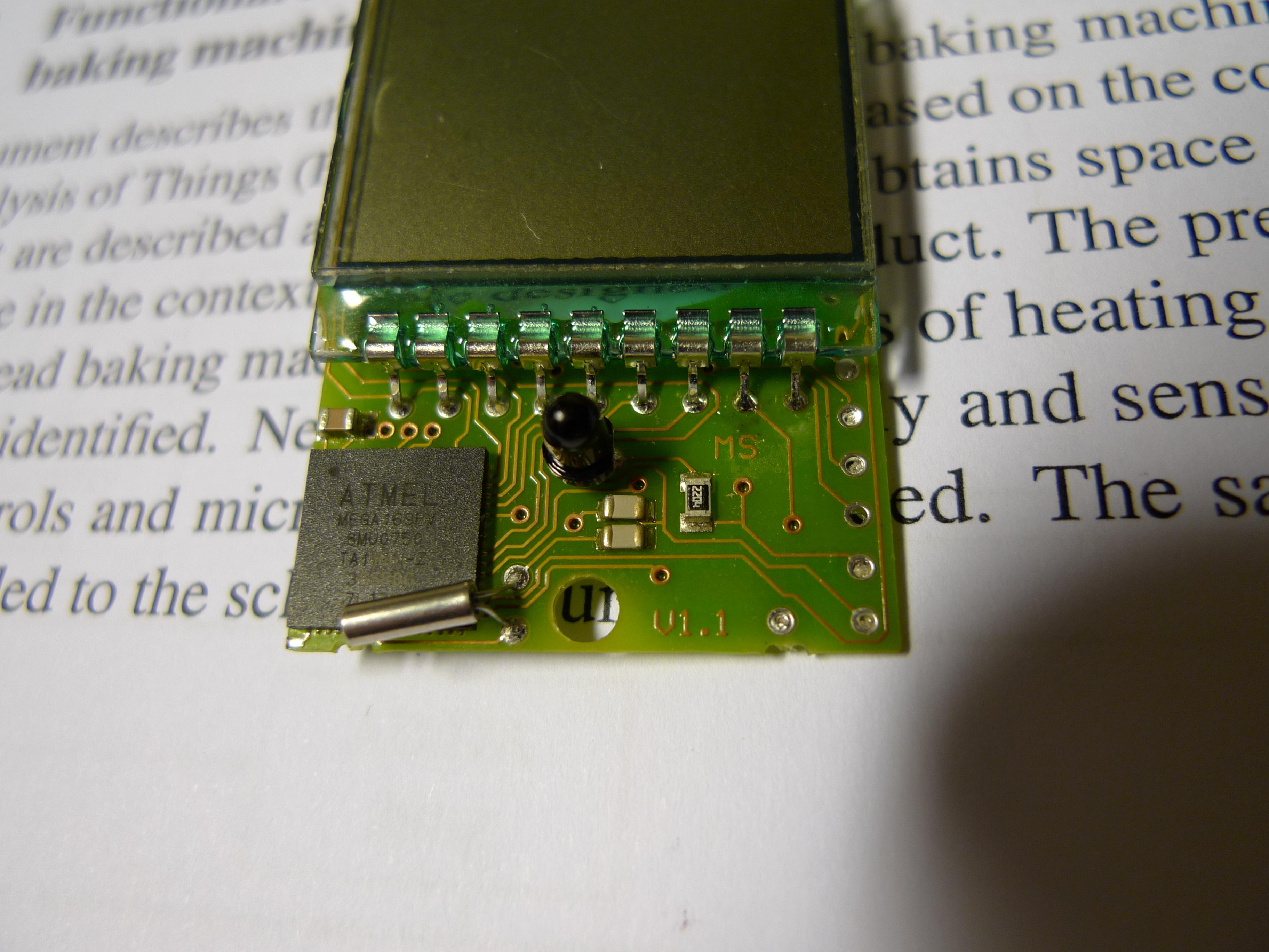
Hi, I got a PCB recently. It is about a numeration system for a chair which receives data from a remote controller and demonstrates the number on the LCD screen. I can recognize the Microcontroller, LCD screen and photodiode in the PCB, but I cannot figure out the other tiny parts. Can somebody help me? Thanks a lot!


The gray parts are capacitors, without markings it is impossible to tell their value.
It looks like they may be connected across the crystal which is the metal cylinder part. If they are across the crystal they will probably be in the region of 22pF in value. Most but not all crystals in this container are 32768Hz.

The black part labeled 2204 (I think) is a resistor, probably 220KΩ.

Brian.
 

Thank you very much. But there is still one tiny yellow thing between the LCD and Microcontroller, in the left side. Can you help me?
 

hi,

resistor value is 2204 this means 220 x 10000 this mean 2.2mega
resistor coding is same as normal package eg. 220k is coaded as 2203 (220 x 1000)


and all other smd components are capacitor.if u tell me crystal value then i can tell u the value of two capacitor linked to it
 

Thanks a lot. The crystal value is 32.768kHz I think, because the number on it is 32768. How can I determine the capacitor value from the crystal? Somebody says that they are about 50uF.
 

Sorry, I missed the 'yellow thing', it's another capacitor. Their appearance is up to the manufacturer but *usually* the light gray ones are small value single layer ceramics with values up to about 1nF, the darker ones are *usually* multi-layer ceramics with higher values. I would hazard a guess the dark one is across the supply pins and would be in the region of 100nF, the light ones connected to the crystal will be in the region of 10pF to 30pf, certainly not in the µF range.

The resistor coding can be interpreted as 220 * 10^4 = 2.2MΩ or if it is a precision resistor, it could be 22.0 * 10^4 = 220KΩ. Unfortunately, with such small components, the manufacturers tend to use their own coding schemes so it can be difficult to tell.

Brian.
 

Thanks. I still don't know why the photodiode is also connected to the crystal?
 

Hi flyewolf,
Maybe you can drow the circuit/try reengineering, these board isnt so complex, it must be possible & clears some questions automatically:)...
K.
 

Status
Not open for further replies.

Part and Inventory Search

Welcome to EDABoard.com

Sponsor

Back
Top