Continue to Site

Welcome to EDAboard.com

Welcome to our site! EDAboard.com is an international Electronics Discussion Forum focused on EDA software, circuits, schematics, books, theory, papers, asic, pld, 8051, DSP, Network, RF, Analog Design, PCB, Service Manuals... and a whole lot more! To participate you need to register. Registration is free. Click here to register now.

Building a custom notch filter

Status
Not open for further replies.

mallyajiggs

Newbie level 4
Joined
Feb 6, 2010
Messages
7
Helped
0
Reputation
0
Reaction score
0
Trophy points
1,281
Location
Providence
Activity points
1,338
Hey guys, sorry not an electronics guy so please help

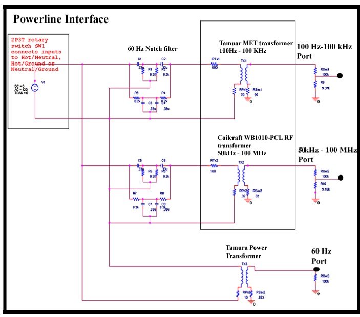
I am building a 60 hz notch filter and have the components for that, but i am not sure on what i can build the circuit ?
This will be connected directly to the mains( residential ac power outlet).

I assume i cannot use breadboards to build this circuit on ?
any suggestions ? other than using a wooden board ?
 

Hi,
Of course, you can build it on a bread board, but YOU MUST BE CARE FOR ENOUGH ISOLATION DISTANCES between mains lines and the rest of world, & secondary electronics too, & you must have some isolations material plate over all touchable parts with main voltage on hes metall contacts......
But; tell it pls: is your circuit on mains part or only on the secondary(after a transformer)?
I think; your data are too suspect/not enough (i.e.: is it a power filter or only for signals_no current of Ampers) for me_sorry.
K.
 
Most audio and video circuits use shielded cable so they don't need a notch filter to cancel mains hum.
Why does your circuit have mains hum?
 

Maybe has GND-loops, or need good shielding technique!?
K.
 

I can't imagine the purpose of a notch filter connected directly to the mains( residential ac power outlet).
It's apparently not intended for audio or video signals.
 

Nobody knows the frequency the notch filter must reduce. Maybe an AM radio station transmitter is next door. A TV station's transmitter?
A weather radar transmitter?
A cell phone transmitting tower?

Why didn't the person who started this thread leave out all the important details?
 

Why didn't the person who started this thread leave out all the important details?
That's the problem, of course. However, the frequency is said to be 60 Hz.
 

Here is the deal guys, i need to filter the AC frequency so that i can increase the dynamic range of sampled data... esentially this notch filter goes before a band pass filter which is like a power interface circuit and then connected to a oscilloscope to sample

But no body seeems to answer my original question ? what are my options on building this circuit ?
Breadboard ?
Custom PCB ?
any other off the shelf materials ?
 

karesz tried to answer your question, others apparently thought, that you can't give a reasonable answer without knowing
the kind of circuit, e.g. if the parts have a few mm size or are large iron core inductors with a several kg weigth and bulky
high voltage capacitors.

If the circuit is a measurement tool rather than the device under test, safety regulations suggest to put it in an enclosure,
either metallic and connected to protective ground or isolating with sufficient isolation strength. This also applies for a lab
enviroment, because you're required to minimize safety risks as far as possible.
 

I have built and I have many very sensitive audio products that are all powered from AC electricity. They do not have and do not need a notch filter.
Why does your circuit pickup the AC frequency?

You mentioned a breadboard so maybe your circuit is built on one and its long jumper wires are antennas that pickup the interference.

Maybe the power supply for your circuit is not filtered properly and has hum.
Maybe your circuit does not use shielded input cables but needs them.
 

as far as the notch filter is concerned, its just capacitors & resitors ? so what would be the ideal material to build on ? -
So far i got suggestions that i should enclose it, but i really want to know if any off the shelf products are available ?

I need to filter 60 Hz just to enhance my dynamic range of data

So this circuit will be connected to mains, then i connect a oscilloscope to read the data into a computer and later analyze it.


Your passive twin-T notch filters must use parts with 1% or better tolerance. If the values are exact then they will reduce 60Hz from the mains down to about 1V. But the harmonics and interference from light dimmers will not be affected and will drown your data.
 
Thanks will keep all of this in mind !

(refer circuit above)
one more question, there is this 60Hz port, from a power transformer (TX3), any idea of what secifications this may be, as far as i know i would need this only to eliminate any sudden surge in voltage
they only seem to specify Rprim =10 & Rsec =0.833, no info abt VA rating etc.. please suggest
 

no, in the bottom part of the circuit i actually need the 60Hz output , its a power transformer which i think is being used to eliminate spikes or surges in current.
 

I'm tempted to make a lot of comments on your "powerline interface". I confine myself to mention, that the "50 kHz - 100 MHz"
has a cut-off frequency of about 1 MHz according to the oscilloscope respectively probe input capitance, may be even lower, if cable
capacitance is added. You surely need a much lower attenuator impedance, 50 ohm output would be probably best.

As another point, at least for the high frequency channel, a first or second order low-pass would provide better performance
with lower part count.
 

Let me just summarize quickly what i am trying to do, i guess i wasn't clear enough earlier.
This circuit diagram is part of something, i just need to reproduce this to analyse data.
It is very important for me to stick to the circuit and not change any components.

Essentially this is an interface circuit for the USB oscilloscope which will be connected to either of the 3 ports depending on the analysis i would require. Also the purpose of 60 Hz notch filter here is to eliminate continous noise produced by devices with motors.
 

It is very important for me to stick to the circuit and not change any components.
It's is up to you. In this case, you shouldn't give the impression, that you want to discuss about circuit details.

If you don't want to change components, you may want to change the describing circuit text to fit the effective specification,
particularly "50 kHz - 100 MHz".

Generally, you should consider the fact, that all contributors to your thread are already experienced in electronic measurements.
 

Sorry, i didn't mean to seem rude...

but i am not an expert, i know little about this circuit but need to reproduce as specified and so seeking expert help
 

Status
Not open for further replies.

Part and Inventory Search

Welcome to EDABoard.com

Sponsor

Back
Top