Continue to Site

Welcome to EDAboard.com

Welcome to our site! EDAboard.com is an international Electronics Discussion Forum focused on EDA software, circuits, schematics, books, theory, papers, asic, pld, 8051, DSP, Network, RF, Analog Design, PCB, Service Manuals... and a whole lot more! To participate you need to register. Registration is free. Click here to register now.

help!!fsk 125kHz rfid reader circuit problem

Status
Not open for further replies.

jeneral_pandeer

Newbie level 6
Joined
Aug 27, 2009
Messages
11
Helped
0
Reputation
0
Reaction score
0
Trophy points
1,281
Location
kuala lumpur
Activity points
1,353
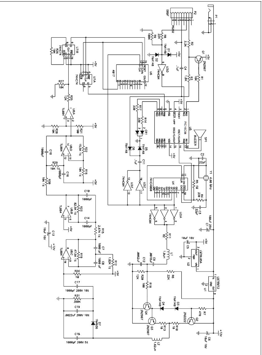
LM78L12ACZ can the voltage regulator supply 12v from 9v??if not can somebody give me any suggestion..i also need help detecting other error in this circuit..thanx!!


Assuming the socket in the top left corner is the power input, it needs to be at least 14V to operate. The 5V rail is OK but the 12V regulator needs at least 2V headroom before it's output is guaranteed to be stable.

Brian.
 

thanx..if i intend to use 9v dc power supply.. what modification do i need to do??can it stiil generate 12v output at the 7812??
 

Hi,
You see, your voltage regulators are so called "analog regulators", they are per specification with absolut minimum 2---3V, eventuell more, over hes output voltage to supply_thes is physics of her electronics:-(.
If you has less as (as betwixt wrote too) min 14V at the input_usually they functions, has some voltage (more or less followed the input value at some lower voltage level), but even: they follows the input voltages & DONT STABILIZE IT!
You has the only way to give over 14 volt to the supply connector!
Otherwise you must change components in the circuit, but the output amp(power output stage!) needs maybe these "higher voltage "for work with a concrete/specified" reader distance"!
Also;
practically is not real to have less as 14-15V for powering!
Or you can_of course_an EXTERNAL 12V STABILIZED voltage CONNECT TO IT, then you must take out the internal regulator(U1) & short the pins 1&3!!
Dont forget: you need in all case an 12V supply for the same reader distance-or output pwr...
Good luck!
K.
 

Your welcome:)
You can -unfortunately- have a (maybe) more coplicated option too:
Take a "step up switcher" on a small PCB between your 9V input and the existent RFID-Printboard:)
You can find a lot of products on the web_firm home-sides; Ithink one of simplest way is to check _www.national.com_than Pwower...Webbench(online design service), select for "Simple Switch)...
I selected short time befor i.e. an step up solution by the way, you can see much possible version, select some and varying the parameters, you becomes the component-prices of your design too:)
I think these is a real good way some and speedy to decide...
K.
 

Only the power amplifier uses 12V so you could try shorting the 7812 out (input to output, isolate the ground pin) and run the whole circuit on 9V.

It should still work but the RFID detection range will be a little smaller as the radiated power will be reduced.

The 7812 is a linear "step down" regulator, it can only produce 12V out when more than 12V (plus 2V extra for its internal circuits = 14V) is present on it's input. If you only have 9V available and you must have 12V, the only solution is to use a "step up" or "boost" regulator which is more complicated and certainly more than a single component!

Brian.
 

I just considered, if the circuit can be slightly modified to achieve the same or even higher output at 9V supply voltage.
But I stumbled upon a completely erratic dimensioning of LC circuits. If the L and C values are correct, both LC circuits have
about 4 MHz resonance frequency, although the 4060 clearly produces a 125 kHz square wave. The circuit has apparently
more serious problems than a somewhat low supply voltage.
 

Well spotted!

It should be 125KHz, the induction coil I use is 700uH, much bigger than the one in this schematic.

Brian.
 

thanx guys..
about the induction coil..it is actually 1.62mH...sorry for the typo..
you guys really helped me a lot in understanding the problem in the circuit..
about the voltage regulator problem....i'm considering some options :
a)use a lm 2577-12 by taking the 5v output from 7805 and boost it to 12v
b)use a 15v power supply for 7805 and 7812
c)use an external 12v for the antenna circuit...

which one do you think is the best??

if you guys detect any other errors feel free to comment,i really appreciate it..thanx!
 

I wouldn't drop to 5V then boost it up to 12 again, that is not the efficient way to do it.

If you need 12V, start with the existing 9V and top it up by 3V. My favorite is the MC34063 which is cheap and will give up to 1.5A out with just 5 other components. Efficiency should be close to 90%.

I still think it might be possible to squeeze more power out of the amplifier at 9V though. Possibly dropping R10 & R13 will help. The only difference the power makes is to the detection range, as it will only be a few cm anyway, you probably wouldn't notice it was a mm or so less.

Brian.
 

@jeneral_pandeer,
Is these 9V pls from a battery, what is your abs. minimal input voltage value to work with the circuit?
K.
 

When you seriously think about saving battery energy, you would surely not use a linear output amplifier. It's the first time I see this
with an 125 kHz or 13.56 MHz RFID sender. Others have a switching push-pull output stage and a filter/impedance matching network.

Thus I don't see much sense in discussing about DC boost converters in this case. The output stage can be your boost converter.
L1 should be also mH by the way.
 

i've made the cicuit and decice that it's ok for the power not to achieve 12v.however i'm now having trouble to test the circuit.can somebody help me??
 

Status
Not open for further replies.

Part and Inventory Search

Welcome to EDABoard.com

Sponsor

Back
Top