Continue to Site

Welcome to EDAboard.com

Welcome to our site! EDAboard.com is an international Electronics Discussion Forum focused on EDA software, circuits, schematics, books, theory, papers, asic, pld, 8051, DSP, Network, RF, Analog Design, PCB, Service Manuals... and a whole lot more! To participate you need to register. Registration is free. Click here to register now.

Inverted Optocoupler output

Status
Not open for further replies.

hbklau

Newbie level 5
Joined
Nov 4, 2009
Messages
8
Helped
0
Reputation
0
Reaction score
0
Trophy points
1,281
Location
Singapore
Activity points
1,346
Hi all,

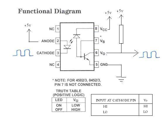
I have some queries over here and hope someone can enlighten me. I am using 6N135 optocoupler and the input to it is coming from a PWM. As per the datasheet, the output will be inverted. However, this is not what i want as I need the actual waveform (Similar to input) to operate a MOSFET for the DC converter. Is there any way to revert the output? I had drawn a connection diagram with a BJT connected at the output. Please advise whether will the output will be revert back?

Next, is it possible to connect a logic gate inverter to the output to just invert the waveform?
 

Hali,
is it a must for you to work with these OC?

Of course, you can drive with these output a logic gate(remember_you need a pull up)_then its specified as TTL-Compatible:)
I think is a discrete solution with an extra PNP transistor & +2 resitors in sum is the other good solution for you. These functions as an inverter too.
K.
 

karesz said:
Hali,
is it a must for you to work with these OC?

Of course, you can drive with these output a logic gate(remember_you need a pull up)_then its specified as TTL-Compatible:)
I think is a discrete solution with an extra PNP transistor & +2 resitors in sum is the other good solution for you. These functions as an inverter too.
K.

Hi sir,

I have to work with the oc. No choice. LOL.

So are you saying it is alright to work with a Not gate and with a pull up at the output? Then what about the BJT at the output? Will it work too? Thanks for the time spend on reading my post.
 

Hi,
I modified the circuit, hopefully it will work fine now.
Remember to connect the power pins properly and the pull-up resistor! Without this, you won't get your proper output.
94_1263229582.jpg
 

Tahmid,
You see, the LED driving is not possible so simple in my opinion, because depend of rest of circuit , what you didnot drowed...
K.
 

karesz said:
Tahmid,
You see, the LED driving is not possible so simple in my opinion, because depend of rest of circuit , what you didnot drowed...
K.

Thanks. I will try it out tomorow when I reach the school and keep you all posted.
 

Hi hbklau,
Be care, that your LED current will be limited!!
Good luck!
K.
 

Hi karesz,
I don't get what you mean.
I used this method before. Always worked for me. The only thing is, you have to limit the current to the LED, which I didn't draw. This will depend on the source.
 

Hi Tahmid,
Yes, I agree w. limiting_ question was for me, what kind of a source drives the diode?
Is it an symmetrical or only a simple transitor stage...
Greatings!
K.
 

Tahmid said:
Hi,
I modified the circuit, hopefully it will work fine now.
Remember to connect the power pins properly and the pull-up resistor! Without this, you won't get your proper output.
94_1263229582.jpg

Hi all,

I had connected a transistor at the Vo of the optocoupler and using a pulled up voltage source. It works. Thanks everyone for the guidance.

Transistor off - - desired output = 5V
Transistor on - - desired output = 0V
 

Hi,
Clear works it_ it was not a question, but dont forget pls a current limiter resistor to applay for your LED, then others will it no long working...
K.
 

Hi,
Good to know it works. But with my method, you would not even need the external transistor, only current limiting for the LED is required.
 

Tahmid said:
Hi,
Good to know it works. But with my method, you would not even need the external transistor, only current limiting for the LED is required.

Are you saying that the resistor before the input?
 

Hi, I know this is an old thread, but i have a device which is the exact same as this one to test, but i need to test the CTR ( Current Transfer Ratio).

Can you advise on how to best test this ?

devicei is
HCPL-0501

Thank you if anyone gets this.
 

Can you advise on how to best test this ?

I wish you gave its model so that the test circuit could be presented with the proper values of its components.

Kerim

Added_1:
Sorry... only now I noticed you did write its model :oops:

Added_2:
Please if you are still interested... just let me know.
 
Last edited:

You are right... I was confused with his mistyped word "devicei" and I didn't expect HCPL as a prefix for an otptocoupler since all I had are something like ?N??
 

Status
Not open for further replies.

Similar threads

Part and Inventory Search

Welcome to EDABoard.com

Sponsor

Back
Top