Continue to Site

Welcome to EDAboard.com

Welcome to our site! EDAboard.com is an international Electronics Discussion Forum focused on EDA software, circuits, schematics, books, theory, papers, asic, pld, 8051, DSP, Network, RF, Analog Design, PCB, Service Manuals... and a whole lot more! To participate you need to register. Registration is free. Click here to register now.

Will this modified programmable current sink work?

Status
Not open for further replies.

powersys

Advanced Member level 1
Joined
Nov 29, 2005
Messages
439
Helped
3
Reputation
6
Reaction score
2
Trophy points
1,298
Activity points
4,981
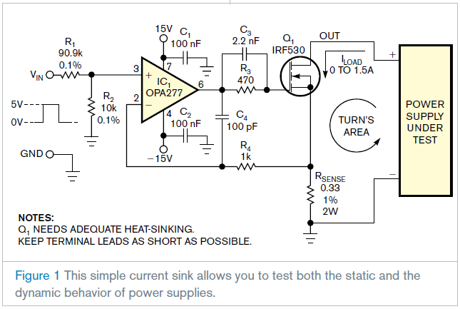
I found a voltage-controlled current sink as following:
**broken link removed**

For the sake of convenience, the circuit schematic in the article is copied and pasted here as Figure 1 below.

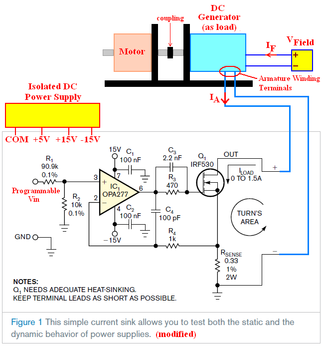
I'm not sure whether I could replace the "power supply under test" with the "armature winding circuit" as shown in the modified figure. Do you think the EMF generated by the DC generator will cause any damage to the circuit? Assume the output power of the DC generator is well below the rating of the circuit in Figure 1 (original).

I plan to use an isolated DC power supply to source the +5V (for programmable input circuit) and +/-15V (for the OPA277). Do you think it is safe to connect the COM of the isolated power supply to the GND of the circuit?

Thanks.


The circuit should be O.K. Consider that MOSFETs are protected against transient voltages by an internal zener clamp.
 

    powersys

    Points: 2
    Helpful Answer Positive Rating
Thanks FvM. If I'm not mistaken, if the temperature of Rsense changes, its resistance will change as well and therefore there might be error in IA or ILoad. Do you have any idea how we can improve this?

Thank you very much

By the way, if I wish to drive this circuit with higher armature current, e.g. 5A, I think I should use a higher power MOSFET. Frankly, I've no knowledge of using MOSFET as linear amplifier, and hence do not know what parameters of a MOSFET are important for MOSFET to be used as linear amplifier. Therefore, I will be very grateful if someone could recommend one for me. The one in Figure 1 uses IRF530 from ST Microelectronis. Can we consider HEXFET MOSFET (which is designed for switching mode application) from IRF?

Thank you very much
 

By the way again, do you think paralleling several IRF530 to have higher power handling capability will be a good option?
 

Hi,
IRF530 is enough loadable for up to ca.15A_if you APPLY the needed COOLING_, their RdsOn in extrems is=< 0.3Ohm, if you have 5V Ugs=> you can use it for min 10-12Amps...

Your max. dissipation is=0.3 Ohmx12Amp=43W, but typically ca. at 25-30W, depending of your concrete junction temperature(efficiency of cooling).

If you are not sure with the FET: their exists in the same package some types for 50-70 Amps too...
K.
 

Simply paralleling of MOSFETs doesn't achieve equal current share. Either an individual source resistor for each FET or selection
of FETs with equal Ugs is necessary. Using a single FET in a package with sufficient power capacity is a more simple solution.
 

Hi powersys,
check pls IRF2807ZSPbf_75V/75A & <15mOhm,
or IRFS3207PbF_75V,170A & < 10mOhm, in the same (D2Pak)package:)
K.
 

    powersys

    Points: 2
    Helpful Answer Positive Rating
I received the following reply from IRF. I'm confusing now. So, can we use MOSFET (e.g. HEXFET MOSFET from IRF) to replace the Q1 in the circuit?

Thanks.
We don't recommend Mosfets used in linear application. IR HEXFET® MOSFETs are designed to be used as Switches. This does not preclude their use in linear applications but as the device technology advances to provide ever better performance as switches with lower Rds(0n) and gate charge figures, this makes the devices ever less suitable for linear applications. A lower Rds(on) equates to an output characteristic with a steep slope, which makes it difficult to maintain a suitable gate bias to keep the drain current operating point stable. As the drain current is deliberately varied in response to an applied input voltage, this changes the dissipated power within the part, changing the junction temperature and thus the value of Rds(on), i.e the slope of the output characteristic.
 

powersys said:
...I'm confusing now. ..Thanks.

We don't recommend Mosfets used in linear application....

Im not an FET expert, but I dont understand it, then the device is in feedbackloop!?
For me is applicable-what are the expert meanings pls?
K.
 

Hi karesz... Thanks again for your reply. I always use MOSFET as switching device. But when come to use MOSFET as linear amplifier, I'm not familiar. Probably experts in this forum can shed some light. Thanks.
 

Hopefully, the IRF support guys know about switching circuits. Unfortunately their knowledge about linear circuits seems to be poor.
Perhaps you should tell them, you have heard that ST, Infineon, IXYS, whatsoever are better suited for linear applications.
They may think again...

To be more specific, your basic circuit may need some optimization if used with very large FETs respectively high gate source and
gate drain capacitances. At worst case, the loop can get unstable.

Simulation or emprical test of your circuit will help you to do the optimization for a particular output transistor choice.

As a general answer, you are able to design linear current sources with MOSFET (or IGBT) at any current level, either
1 or 1000 A. You possibly need additional voltage followers to drive the gate capacitances and have to adjust the
loop compensation of course.
 

    powersys

    Points: 2
    Helpful Answer Positive Rating
Let's say now I wish to replace Q1 with another MOSFET with higher power handling capability (e.g. IRFP264). I find out the total gate charge Qg of higher power MOSFET is always higher. By way of example, the Qg of IRF530 is 21nC, whilst the Qg of IRFP264 is 230nC. Do you think the OPA277 in the circuit is enough to drive IRFP264? Is there any formula to determine whether the output of an opamp is enough to supply the total gate charge of a MOSFET?

Added after 9 minutes:

By the way, do you think the modified circuit can provide a current regulation at +/-0.1A?

Which part of the circuit that I need to pay attention in order to achieve +/-0.1A?

Thanks.

Added after 25 minutes:

Vishay IRL530 is denoted as LOGIC MOSFET.
Do you think this type of MOSFET is suitable for the application in the modified circuit?
By the way, what is the difference between ordinary MOSFET and LOGIC MOSFET? I can't spot the difference.

Added after 18 minutes:

In fact I wish to have two different programmable current sink, i.e. one with higher power handling (0~5A) and another one with lower power handling (0~200mA). I wonder, if a proper MOSFET is used to replace Q1, the modified circuit can be used for 0~200mA current sink. Kindly advise.
 

Status
Not open for further replies.

Similar threads

Part and Inventory Search

Welcome to EDABoard.com

Sponsor

Back
Top