Continue to Site

Welcome to EDAboard.com

Welcome to our site! EDAboard.com is an international Electronics Discussion Forum focused on EDA software, circuits, schematics, books, theory, papers, asic, pld, 8051, DSP, Network, RF, Analog Design, PCB, Service Manuals... and a whole lot more! To participate you need to register. Registration is free. Click here to register now.

Question on result of ADC preceded by DAC

Status
Not open for further replies.

donehere

Newbie level 3
Joined
Jan 2, 2010
Messages
4
Helped
0
Reputation
0
Reaction score
0
Trophy points
1,281
Activity points
1,327
Hello,

I guess I'm facing Analog to Digital and vice versa artifacts, and need some help.

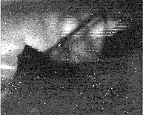
Ok, I have a digital image and I firstly do DAC and then I do ADC. My original image is on the left and on the right is the DAC->ADC processed one:

1_1262450269.gif
62_1262450299.gif


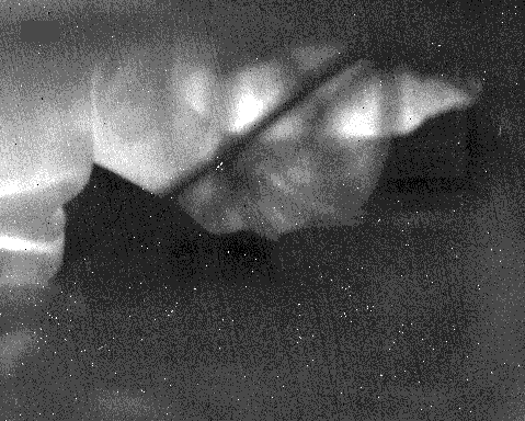
Since the images above have such low contrast, the adjusted ones are below:
26_1262450367.gif
79_1262450388.gif


If you look at last two images, there are two obvious differences,

1. There is the interlacing artifact.
2. Dead pixels, which are represented as white dots, on the original image appear as horizontally amplified on the processed image. I mean a single white dot is replicated as several white dots horizontally adjacent to each other.

I know why (1) occurs, but I am not quite sure on the reason for (2). My guess is somewhere during the DAC and ADC, analog circuit components can't keep up with the sharp contrast between the dead pixel and the pixels on the right and on the left next to the dead one.

If you look at the first two images (low-contrast) ones, what you see is that they have the same number of white pixels (dots); but when I adjust the contrast I discard some of light-gray pixels and make them completely white, and they appear as white pixels next to original dead white pixels (ODWP). This suggests, in the processed image, pixels adjacent to ODWP are a lighter shade of gray compared to the pixels in the original image; which makes me think DAC or ADC circuit can't jump from zero white to some contrasting dark gray or vice versa. Instead it does the transition in several pixels.

What do you think, do I have reasonable arguments or am I completely missing the point?

Thanks in advance.[/img]
 

It seems to me, that a lot of information is missing from your post, e.g.
- involved analog video standard (interlaced?)
- AD and DA sampling frequency and resolution
- sync processing details
 

Thanks for your reply FvM.

- involved analog video standard (interlaced?)
Yes, it is interlaced and it can be seen from the processed images.

- AD and DA sampling frequency and resolution
I have no idea about the sampling frequencies as I use a video processing card to do the DA sampling and an analog frame grabber to do the AD sampling. I checked the documentation for both products and I couldn't find any information.

Resolution is 704x576 (PAL) and since I am only interested on a specific region I cropped 479x384's off the original images. But still, the pictures I posted are in true resolution which means they are not re-sized.

Edit: It just occurred to me that you might be asking the field or frame rate. It is PAL (50 Hz field, 25 Hz frame)

- sync processing details

I didn't do signal processing in the past so I don't know what you are referring to by sync processing.
 

just a guess: it could be that the dac cannot properly drive the adc. Can you show a very small crop around the dead pixels? If it is a bandwidth problem, you will see the intensity go gradually from dark to light and viceversa.
 

    donehere

    Points: 2
    Helpful Answer Positive Rating
just a guess: it could be that the dac cannot properly drive the adc. Can you show a very small crop around the dead pixels? If it is a bandwidth problem, you will see the intensity go gradually from dark to light and viceversa.

Here is my crops, again from the original and the processed images. These crops are from ones that are not contrast or histogram adjusted.

[Processed image (right one)] = [Original image (left one) ->DAC -> ADC]

37_1262461076.gif
71_1262461091.gif


JoannesPaulus: What you suggested seems to be true. Could you please explain more what is happening here. In what circumstances a DAC cannot properly drive an ADC?

Thanks.
 

it could be that the dac cannot properly drive the adc
More generally, the involved analog signal processing may be part of the problem. Most likely it's not just a DAC port driving
an ADC! Video encoder circuits have usually analog low-pass filters and additional anti-aliasing filters may be used at the
frame grabber.

I doubt, that you can expect a lossless respective undistorted signal reproduction from the enocder and decoder signal chain.
There are, by the way, different video interfaces that are providing different signal quality. FBAS composite must be expected
the worst of them, most likely a low cost frame grabber has no other interface.

The said artefacts can be e.g. caused by a non-ideal operation of the color signal path. If the image is b/w only, you can try
to output a BAS respectively Y signal without modulated color component at the video encoder.

You didn't tell at all, what's the purpose of feeding a digital image to the DA/AD chain.

I couldn't find any information
By identifying the encoder and decoder chip sets used in the products, you can get the respective datasheet information.
Basic data are almost similar between industry standard chip sets however, because they simply reproduce common
digital video standards.
 

    donehere

    Points: 2
    Helpful Answer Positive Rating
Video encoder circuits have usually analog low-pass filters and additional anti-aliasing filters may be used at the
frame grabber.

So, these erratic white dots are regarded as high frequency components and get distorted? I am not a DSP guy but I think a low-pass filter should have a visual smoothing effect on the image; and gradual transition from white to gray and viceversa is how I correlate the result to filtering with my limited knowledge.

Can an anti-aliasing filter have an effect in my case? Do I have fine detail to cause aliasing? I don't change resolutions at all.

FBAS composite must be expected
the worst of them, most likely a low cost frame grabber has no other interface.

You didn't tell at all, what's the purpose of feeding a digital image to the DA/AD chain.

I am using FBAS (CVBS) signal.

I am trying to assess the qualities of my video processing card. It has simultaneous digital and analog outputs; and digital output being the primary one, analog output is generated from the digital output. I will be using both outputs and need to know raw or processed analog output is good enough for me.
 

Status
Not open for further replies.

Similar threads

Part and Inventory Search

Welcome to EDABoard.com

Sponsor

Back
Top