mr_shern
Newbie level 3
- Joined
- Dec 15, 2009
- Messages
- 3
- Helped
- 0
- Reputation
- 0
- Reaction score
- 0
- Trophy points
- 1,281
- Location
- Paradise without antennas
- Activity points
- 1,300
Hello everyone! I have been in trouble with patch antenna feeding by CPW cause I don't know how to draw and set the model in feko Suite 5.2. My antenna is patch one with stripline applying for UWB. I'm expecting some examples or tuts that help me to figure out the problem.I did search a lot in the forum but it's hopeless so if anyone got any clue I appreciate that.
Here is my antenna:

[/img]
Here is my antenna:
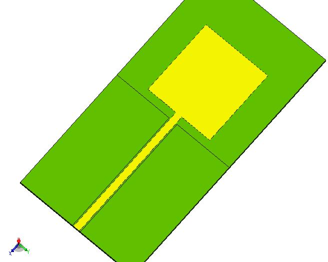
[/img]
