Continue to Site

Welcome to EDAboard.com

Welcome to our site! EDAboard.com is an international Electronics Discussion Forum focused on EDA software, circuits, schematics, books, theory, papers, asic, pld, 8051, DSP, Network, RF, Analog Design, PCB, Service Manuals... and a whole lot more! To participate you need to register. Registration is free. Click here to register now.

10v to 5.5V voltage regulator

Status
Not open for further replies.

gilbertomaldito

Full Member level 3
Joined
Aug 21, 2006
Messages
159
Helped
4
Reputation
8
Reaction score
3
Trophy points
1,298
Activity points
2,385
Hi Voltage regulator experts,

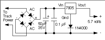
I would like to ask what would be the best type/design of Voltage Regulator for a 10v input - 5.5V output requirement.

Please enlighten me.

Analog Designer,

--andrew
 

Hi HAMEEDS01,

Actually I do not know. All I know is that this Vout=5.5V will serve as the Power Supply of my internal circuits (like amplifiers, digital blocks, other analog blocks that requires 5.5V). Because I have 2 types of circuits inside one IC design, one which requires 10V and other requires 5.5V. But since I have the 10V from external already, I need to design my 5.5V voltage regulator.

About the current required you are asking me, do I need to take note of this? My 5.5V will just serve as my power supply(Vdd) to my circuits designed.

Please enlighten me and give me wisdom about this.

This is my application: **broken link removed**
please go to page 7, and you will see the INTERNAL REGULATORS Block at the upper middle of the BLOCK DIAGRAM.

--andrew
 

I checked the said datasheet and the given application circuits. It's pretty clear, that the device doesn't need an external 5.5V voltage regulator, just a 8 to 12 V Vcc.
 

Hi FvM,

Yes, I dont need 5.5V external regulator. I need 5.5V internal to power up some circuits requiring 5.5V power supply. So Vcc will be my input for the voltage regulator to produce vout=5.5V.

I tried to search for a good reference for my 10v in-5.5Vout internal regulator .... I couldnt find any.

please help.
 

I don't understand what you are trying to achieve. Is it a chip design project?
 

Hi FvM,

yes. its a chip design project.

--andrew
 

Use zener diode with transistor reg circuit or Lm317 reg circuit
 

This is also my problem :)

In general it depends on the technology used. So for this kind of application I hope I can go on HV technologyes, that have transistors that can withstand 12V or more.
Also the pass transistor would be preferably a DMOS device, but I am wondering how do I supply the driver for the DMOS.
Some people say I showld make a pre-regulator, maybe using a zener diode available in the technology, if there is one available :)

Hope I helped and you can also help me...
 

If the requirement of 5.5 volts is not that precise, one may go for a simplest way of using a 7805 regulator which will yield 5volts. Or to get precise 5.5 volts, LM317 may be used....Cheers
 

I think it is about an integrated voltage regulator so discrete components would not work :)
 

integrated 7805 regulator with one diode on the gnd pin and you will get 5.7v which should be what you need in fact. regards,

7805_boosted.gif
 

If you're noise sensitive and power insensitive, then a linear
is the easy way out. At low currents and not much load
ripple / spike current you might not even need to have
off-chip decoupling.

Distributing smaller, local regulators around the chip may
give you better results than a single big boy, especially
if some blocks are "busy" you can keep their noise out of
the rest, provide each one only the capacitance it really
needs, etc.

How much current, is your #1 question. More than 100mA,
you have some hard thinking to do. Less, just do the linear.
 

Status
Not open for further replies.

Similar threads

Part and Inventory Search

Welcome to EDABoard.com

Sponsor

Back
Top