Continue to Site

Welcome to EDAboard.com

Welcome to our site! EDAboard.com is an international Electronics Discussion Forum focused on EDA software, circuits, schematics, books, theory, papers, asic, pld, 8051, DSP, Network, RF, Analog Design, PCB, Service Manuals... and a whole lot more! To participate you need to register. Registration is free. Click here to register now.

duty cycle problem - change from 50 to 10-20%

Status
Not open for further replies.

rky

Junior Member level 1
Joined
Nov 13, 2009
Messages
17
Helped
0
Reputation
0
Reaction score
0
Trophy points
1,281
Location
india
Activity points
1,380
duty cycle problem

hi..........
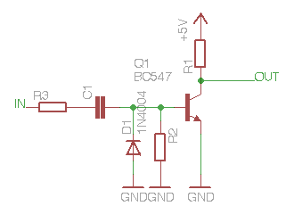
i have problem to change the duty cycle....
i have i/p of 9 volts square wave of 50% duty cycle....
but i want to change that 50% to 20%-10% duty cycle......
anybody plz help me out....how can i achieve???
thank you
rky
 

Re: duty cycle problem

One option is to feed this 50% square wave to 555-timer (monostable operation) and adjust R-and-C so the output wave has required 10-20% duty cycle ..
Here is info on how to calculate T[on] with 555-timer:
http://www.kpsec.freeuk.com/555timer.htm

Rgds,
IanP
 

Re: duty cycle problem

will 555 works on 3Mhz frequency????
because my frequency is of 3Mhz and duty cycle of 50%.
 

duty cycle problem

No, Dont use 555, use any microcontroller

Nandhu
 

Re: duty cycle problem

how can i use controller???
is pwm comes in picture???
is pwm can generate 3Mhz of frequency????
 

duty cycle problem

You can use any microcontroller that has pwm facility inbuilt. For example atmega 8 has three pwm channels with operating freq of 16MHz. You can easily generate 3mhz pwm with that

Nandhu
 

actually i am familiar with pic controllers......
do you have any idea how to configure pic controller for 3Mhz frequency pwm generate.....
 

Which programming language do you use program??
 

i am using c programming language....
and using CCS C compiler
 

If you are using a IDE used for developing PIC projects, then there must be definitely some built in routines to handle peripheral features commonly available in PIC's. And PWM is one them. Following are the steps to initialize and use the PWM for PIC18F452.

1. Specify the required period and duty cycle.
2. Choose a value for the Timer 2 prescaler (TMR2PS).
3. Calculate the value to be written into the PR2 register
4. Calculate the value to be loaded into the CCPR1L and CCP1CON registers
5. Clear bit 2 of TRISC to make CCP1 pin an output pin.
6. Configure the CCP1 module for PWM operation using register CCP1CON.

These are the general steps. Refer to the datasheet for equations, for calculating values

But use above steps only and only if there are no built in PWM establishing functions available in the IDE being used by you.
 

dont knw but i cant get freqency........
have you code??
 

I would just use a fast non retriggerable monostable multivibrator (monoflop) ic. There exist many of them, which can handle 3 MHz.

Or you can make a simple monoflop circuit yourself using a mosfet or transistor:
35_1259782103.png
 

do u have values of resistor and caps??? for 3Mhz........
and which ic u ve used??
 

Most of microcontrollers and one-shots are just to slow for this job .. not many of them can deal with pulses in the [ns] region ..
You may, however, consider the 74121 (basic TTL version) .. see:
http://www.scarpaz.com/Documents/AN-366.pdf
but you will have to convert the input and output levels from 9V to <5V ..

For Tw≈30ns ==> R=1.5kΩ and C=27pF ..
see: Typical Output Pulse Width vs. Timing Components at the above URL ..

Rgds,
IanP
 

Have a look at this overview of the differences between the standard IC families.

A 74LS, 74ALS or 74HC will already easily do the job. Just chose one that can do a monoflop function, e.g. the 74HC121 that IanP has mentioned.

And there exist still much faster families (e.g. ECL series)
 

Status
Not open for further replies.

Part and Inventory Search

Welcome to EDABoard.com

Sponsor

Back
Top