Continue to Site

Welcome to EDAboard.com

Welcome to our site! EDAboard.com is an international Electronics Discussion Forum focused on EDA software, circuits, schematics, books, theory, papers, asic, pld, 8051, DSP, Network, RF, Analog Design, PCB, Service Manuals... and a whole lot more! To participate you need to register. Registration is free. Click here to register now.

TTL output at serial port without ext.hardware???

Status
Not open for further replies.

adamarul

Junior Member level 3
Joined
Mar 26, 2009
Messages
28
Helped
0
Reputation
0
Reaction score
0
Trophy points
1,281
Location
Chennai,India
Activity points
1,542
ttl output

hi all,
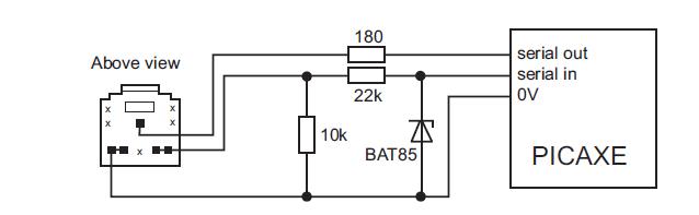
is it possible to get TTL output at serial port without using any external harware (like max232).if not is it possible to interface USB port directly to the AT89S52 microcontroller??

my aim is to design a programmer for AT89S52 without any exteranl hardware!!!!
 

using serial port to output ttl

both the questions results to NO

this all depends on the electrical specification of the communication format
clearly the RS-232 (serial port) has a electrical voltage specification of -15 to -3 V and then +3 to +15V
similarly the USB also uses differential voltage technique
 

output of serial port

Noooooooo

And be carefuly may be u 'll damage u hardware
be carefully
 

connect serial port ttl to pc

It's possible (and quite simple) to interface a microcontroller (like a PIC or an Atmel) to a real standard RS232 port like a COM on a desktop PC (some notebooks don't have real standard RS232 ports) using very few passive components.

The following schematic is taken from PICAXE documentation and it works very well

18_1251291570.jpg

(from https://www.rev-ed.co.uk/docs/picaxe_manual1.pdf pages 37-38 )

Just pay attention that ICs like MAX232 are "inverter drivers" so if you want to use this circuit, you need to use software UART (with inverted outputs) or use hardware inverters at the pins (like a properly connected 74HC00 or so).
 

ttl com port

Be careful, I have no idea what the serial output circuit is on a PICAXE but a normal RS232 port will, as stated above, produce negative as well as positive voltages at its outputs. If the schematic shown by Arkham00 is used to drive TTL ICs it will probably work but CMOS devices will likely be damaged by the negative voltages. The chips internal protection diodes will try to clamp the voltage but I wouldn't rely on them.

Brian.
 

ttl output from pc

Brian,
PICAXE18 is just a plain Microchip PIC16F88 and uses standard I/O pins for a software-only UART so that simple circuit is based on the input diodes of the CMOS port to protect against the negative voltage of the RS232 standard. The resistors in series with the pins are used to limit the current in clamp diodes in every case.

I've used a couple of PICAXEs with this circuit to connect to PCs without problems and I know that PICAXE is quite used, expecially in technical schools in England: they used this very simple approach just to have a very cheap connection link that every student could buy.

But sure: this circuit is just a "dirty trick" :D
 

serial ttl picaxe

I understand.

I was wasn't concerned about protecting the PICAXE from negative inputs, I can see the diode doing that. I was worried about the PICAXE producing negative output that would damage other equipment. I didn't realize it only used I/O pins, I assumed it followed the RS232 standard.

I always design PIC project from scratch so I have no experience of ready made modules. I'm wiser now (and will probably avoid PICAXEs in the future!).

Brian.
 

Status
Not open for further replies.

Part and Inventory Search

Welcome to EDABoard.com

Sponsor

Back
Top