Continue to Site

Welcome to EDAboard.com

Welcome to our site! EDAboard.com is an international Electronics Discussion Forum focused on EDA software, circuits, schematics, books, theory, papers, asic, pld, 8051, DSP, Network, RF, Analog Design, PCB, Service Manuals... and a whole lot more! To participate you need to register. Registration is free. Click here to register now.

coding switch using MICROC c complier

Status
Not open for further replies.

evaang2003

Newbie level 6
Joined
May 28, 2009
Messages
14
Helped
1
Reputation
2
Reaction score
1
Trophy points
1,283
Activity points
1,436
pic16f877 projects

hi, i m a beginner in pic.
currently, i have a project which to display text in lcd screen using pic16f877.
i need to build the hardware as well as the soft ware.

however, i don't really know how to write the source code using c language.
the connection between lcd and pic and elctronics.

can someone give some guidance?( pls provide schematic diagram if possible)

thanks!
 

pic16f877a projects

Evaang2003, the electronics for the LCD should be quite simple. First you need to decide if you want to use 8bit or 4 bit communication. If you're using that PIC only for the LCD (it doesn't work with something else at the same time) you should probably use 8bit communication since it's a lot simpler. I used PORTD for the "data" and PORTC for the other connections, since that's what seemed best for what I was doing.

Now, you need to connect all 8 pins of PORTD to the D0-D7 lines of the LCD. The three remaining lines (E, R/W and RS) can be connected to any I/O port of the PIC (PORT-C Used in this example). The power for the LCD (Vdd, Vss) should be connected to the same power supply as the PIC, and the Vo (or V0 or Vlcd) should be connected to a potentiometer for setting the contrast (or for test purposes you can connect it to Vss).

The initialization sequence (mandatory) for the LCD is described in any datasheet, and you need to follow those steps to get it set up. Once you've done that, it's just a matter of placing ASCII codes on PORTD (data out) and flicking "E-byte" on and off to signal the LCD that the data is valud.

So, for example (pseudo-code):

PORTD = E
PORTC.E = true
Wait 5uS <- wait five microseconds
PORTC.E = false

This should put the letter "E" on the LCD screen (and also move the cursor to the next position).

You can find some info here, as well: **broken link removed**
 

pic16f877 project

Hi Evaang2003
As u r beginner in PIC... I would like to discuss some basics abt PIC / LCD interfacing with u. A simple example program will also be posted.

LCD.JPG

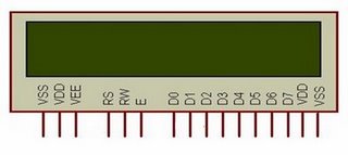
LCD PIN OUTS
92_1243833843.jpg

(From left to right)

Vss- Ground

VDD- Power 5V

VEE- LCD Contrast Adjustment

Control Signals

RS- Register Select

There are 2 very important registers in LCD

* Command Code register
* Data Register

If

RS=0 à Instruction command Code register is selected, allowing user to send command

RS=1 à Data register is selected allowing to send data that has to be displayed.

R\W- Read\Write

R\W input allows the user to write information to LCD or read information from it. How do we read data from LCD????? The data that is being currently displayed will be stored in a buffer memory DDRAM. This data could be read if necessary.

If

R\W=0 à Reading

R\W=1 à Writing

E- Enable

The enable Pin is used by the LCD to latch information at its data pins. When data is supplied to data pins, a high to low pulse must be applied to this pin in order for the LCD to latch the data present in the data pins.

Eà Toggle

Data Bus- D0-D7

Power for Backlighting LEDs

VDD-Power 5V

Vss- GND


General Explanation

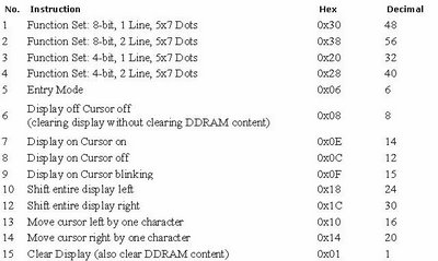
We have to prepare an LCD properly before the character we need, has to be displayed. For this a number of commands have to be provided to the LCD before inputting the required data. The commands will be discussed in the later part of this tutorial.

LCD doesn’t know about the content (data or commands) supplied to its data bus. It is the user who has to specify whether the content at its data pins are data or commands. For this, if a command is inputted then a particular combination of 0s and 1s has to be applied to the Control lines so as to specify it is a Command on the other hand if a data is inputted at the data lines then an another combination of 0s and 1s has to be applied to the control lines to specify it is Data. (Hope you are not confused!!!!). The combinations are as follows-

If

Command à RS=0, R\W=0, E=1\0

Dataà RS=1, R\W=0, E=1\0

Various Commands used in LCDs

5_1243834123.jpg

Interfacing with PIC
untitled.JPG

Here 2 ports PORT B and PORT C of PIC 16F877A is taken. PORT B is used for providing control signals and PORT C is used for providing Data signals.

Of which pins of PORT B are specified as below.

RB0à RS

RB1à R\W

RB2 à E


Programming Steps

1) Before sending Data to be Displayed to the LCD, it should be prepared to hold that particular value.

2) For this certain initializations are to be done as per the Instructions.

a. Move Value 0X38, 3 times.( Applied max 3 times due to rise time factor)

b. Move Value 0X06, 1 time.

c. Move Value 0X0F, 1 time.

3) After each initializations command function and delay should be called.

4) After Initialization Move Data to the LCD

5) Call the Data Function and delay.

( 2 functions , one for command and the other for data is being written for the simplicity of the program)

Program

#include"pic.h"

#include"delay.h"

void main()

{

void command(); //function for command manipolation

void data(); //function for data manipulation

int i;

char a[ ]={"haripanangad"};

TRISC=0X00; //Made Port C Out put port (to use with in main function)

TRISB=0X00; //Made Port B output port (to use with outer function)

DelayMs(1);

PORTC=0X38; //to select the mode of the LED 0X38 - 8 bit 2 lines

command(); // Call command function

DelayMs(1);

PORTC=0X38; //to select the mode of the LED 0X38 - 8 bit 2 lines

command(); // Call command function

DelayMs(1);

PORTC=0X06; // to activate entry mode

command();

DelayMs(1);

PORTC=0X0F; //to get a blinking curser display

command();

DelayMs(1);

for(i=0;i<12;i++)

{

PORTC= a;

data(); //To show that the given values are data

DelayMs(1);

}

while(1);

}


void command() //command function definition

{

RB0=0;

RB1=0;

RB2=1;

DelayUs(1);

RB2=0;

}


void data() //data function definition

{

RB0=1;

RB1=0;

RB2=1;

DelayUs(1);

RB2=0;

}
 

pic16f877 lcd

thanks.
i now working on my project.
i have lcd HD44780A00 type.
however, i need the datasheet.
can anybody show me where can i got it?
 

pic16f877a project

ok....the data sheet is available from the link below....

**broken link removed**

Click PDF Data Sheet in the page to download....
 

pic16f projects

Haripanangad what kind of compiler did u use?
 

pic16f project

here is the attachment
 

Re: pic16f877 lcd project

can you please post a similar code for 20x4 lcd
 

Re: pic16f877 lcd project

saikarthik said:
can you please post a similar code for 20x4 lcd

Which compiler r u using?
You can search for LCD example folder of ur compiller. If u need code in CCS just post(LCD or GLCD).
 

Re: pic16f877 lcd project

i am using micro c can u please post for it
 

pic16f877 lcd project

Hi saikarthik,
For mikroC, there is a library routine already made for LCD. Look in the Help option under the Help menu and choose Hardware Libraries then LCD Library.
Tahmid.
 

Status
Not open for further replies.

Similar threads

Part and Inventory Search

Welcome to EDABoard.com

Sponsor

Back
Top