Continue to Site

Welcome to EDAboard.com

Welcome to our site! EDAboard.com is an international Electronics Discussion Forum focused on EDA software, circuits, schematics, books, theory, papers, asic, pld, 8051, DSP, Network, RF, Analog Design, PCB, Service Manuals... and a whole lot more! To participate you need to register. Registration is free. Click here to register now.

urgent! pls help me with DC gain

Status
Not open for further replies.

sunli567

Junior Member level 1
Joined
Jan 4, 2009
Messages
17
Helped
1
Reputation
2
Reaction score
0
Trophy points
1,281
Activity points
1,402
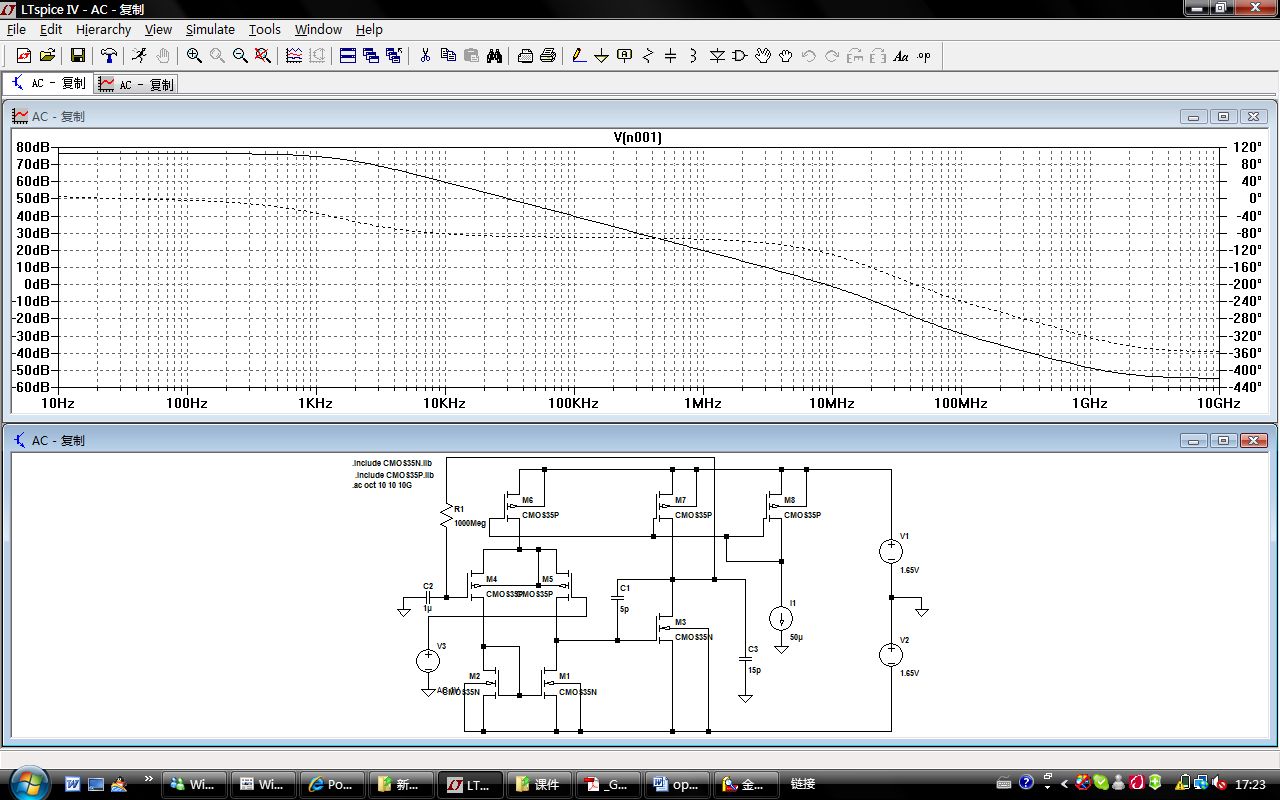
I am designing an two-stage opamp.
Following one is my circuit.
I use this equation to calculate the DC gain, which is 3227(714db).
gm5(rds5//rds1)gm3(rds3//rds7)
But the simulation result given by LTspic is 76.4db, about 6606 times.
why is it so large? but the other parameter is nearly the same as the ones calculated.
pls help me!
thanks!
 

3227 from hand calaculation?
6606 from simulation ?

I think your hand calculation is on a single-ended opamp and simulation circuits of opamp is differential. so the magnification is double.
 

The formula you use is correct. May be you can post the values of gm and rds. And BTW, don't you think M8 should be diode connected? Check that the bias of your amp is what you expect.
 

sutapanaki is right, M8 should be diode connected.

for the calculation, you may use the op data read from the simulator so that your hand calc will be exactly same as simulation

second, check you gain simulation schematic (not available here)
 

yeah, that circuit is not correct for M8.
This test circuit is correct.


gm5 is 314uA/V
rds4= rds5=480kohm
gm3=1648.5uA/V
rds3=rds7=60kohm
DC gain should be 71.7db.

although there will be difference between the real value and the hand calculation, it seems to large. I test the output of circui in AC model, am I right?
I test the first stage DC gain. It is the half of 74db.
 

Actually, we'll need also the rds of M1. Are you sure that rds of M3 is equal to that of M7? Also, the values that you posted, are they what the simulator gave you, or the ones you calculated?
 

Joyes statement is correct; the equation you are using is for differential gain. But you are using it as an single ended version, hence the DC gain is twice the differential gain.
 

Not sure that what you're saying is correct. Don't forget that the active load (current mirror) of the differential pair forces the output current of that stage to be 2x bigger than the current in each differential transistor alone.
 

Hi, everyone. Thanks for your help.
This design is based on 55deg phase margin. Then i change it to 60deg and recalculate the size of each transistor. Finally, it works.
I think some mistakes in calculation cause this happen.
The simulation of improved design gives the same result of hand calculation.
 

Happy to hear you fixed it. Although, the DC gain should not be dependent on your phase margin. If, of course, the worse phase margin is not a result of some screw-up with the biasing of the circuit.
 

Status
Not open for further replies.

Part and Inventory Search

Welcome to EDABoard.com

Sponsor

Back
Top