Continue to Site

Welcome to EDAboard.com

Welcome to our site! EDAboard.com is an international Electronics Discussion Forum focused on EDA software, circuits, schematics, books, theory, papers, asic, pld, 8051, DSP, Network, RF, Analog Design, PCB, Service Manuals... and a whole lot more! To participate you need to register. Registration is free. Click here to register now.

with strong antenna signal, output polarity is reversed !!

Status
Not open for further replies.

flyback2

Junior Member level 1
Joined
May 18, 2001
Messages
17
Helped
1
Reputation
2
Reaction score
1
Trophy points
1,283
Activity points
56
strong antenna

I have a quite strange problem:
I am developing a ASK receiver at 433MHz, modulated by a digital stream at 4K baud. When the transmitter and receiver are quite near (about 40cm) , the receiver RF front end will saturated (I think so), and the demodulated output stops working. With a distance of 35cm, the output reappear but is in exactly in reversed polarity. How can I explain this behaviour?
Regards
 

strong antenna

What type of receiver are you using? Is it a super regenerative or "ASH" receiver, or just a normal superhetrodyne?
 

antenna signal receiver

The chip I am using is the Philips (NXP) UAA3220, wired as a ASK superheterodyne receiver. I guess that the mixer stage, once overloaded, reacts oddly.
I also observe the same behaviour in a completely different system: a 125KHz RFID using Atmel U3280M(tag) /U2270(reader). When the coils are very close, the U2270 may decode the reversed signal transmitted by the U3280M.
 

u3280m forum -datasheet

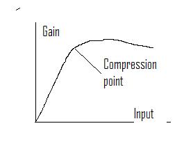
Is it possible for a rf amplifier, the gain decreases with increased input signal (in heavily overload condition, far past the compression point)?. I don't have enough equipment to verify this behaviour.
 

output polarity

Well, these types of chips just look at the RSSI output, and decide if the amplitude is there or not. So the first test I would do is to hook an oscilloscope probe to the RSSI output, and a 2nd probe to the data output, and try to see what the heck is going on. There might be some ringing or something that the data slicer thinks is a rising edge at the wrong point in time. You can screw around with the cpa/cpb pins to maybe fix some ringing.

It is possible that the ASK transmitter does not have a very good extinction (in other words, even when you are transmitting a "0", there might be a lot of RF coming out of the antenna). If there is not clear ON/OFF of the RF energy, then the RSSI might get confused. Also, there might be some other leakage frequency getting picked up by the receiver as the transmitter gets too close.

Rich
 
Last edited by a moderator:

signal output of an antenna

Hi Rick
So far, I poke the rssi signal according to your advice:
- if the distance is far enough, the rssi shows a good variation according to the modulation signal.
- when I reduce the distance, this variation becomes smaller but is still in phase. the rssi signal grows up to the max
- there is a point when variation is too small for the data slicer. rssi is at max.
- after that, the rssi is still at max, but a (very small) variation reappears with opposite phase. There are no ringing or spikes.
I'm sorry that I don't have screen snapshot (i will do it later when I come back to work)
I suppose that the behaviour of the rf amplifier is as the attached bitmap, so
when the transmitter sends a "0", there are enough residual rf reaching the receiver which deliver a highest rssi voltage
when the transmitter sends a "1", the receiver is so heavily overloaded (working far from the compression point), and delivers a slighly lower rssi.
In your opinion, is it possible that such condition can occurs?
I will try to confirm with more "scientific" equipment later.
Lang

19_1241627776.jpg
 

u2270 distance

Well, it just sounds like it is overloaded. If you have range to spare, you can add a fixed attenuator. If not, you can add a variable attenuator, like a pin diode, in front of the receiver. You would monitor the RSSI average DC voltage, and when it got high enough, you would send some forward bias DC current into the shunt mounted PIN diode.

Rich
 
Last edited by a moderator:

Status
Not open for further replies.

Part and Inventory Search

Welcome to EDABoard.com

Sponsor

Back
Top