Continue to Site

Welcome to EDAboard.com

Welcome to our site! EDAboard.com is an international Electronics Discussion Forum focused on EDA software, circuits, schematics, books, theory, papers, asic, pld, 8051, DSP, Network, RF, Analog Design, PCB, Service Manuals... and a whole lot more! To participate you need to register. Registration is free. Click here to register now.

stability of a system from the frequency analysis

Status
Not open for further replies.

bharathr87

Member level 1
Joined
Jan 27, 2009
Messages
34
Helped
0
Reputation
0
Reaction score
0
Trophy points
1,286
Activity points
1,482
transistor 1gmp

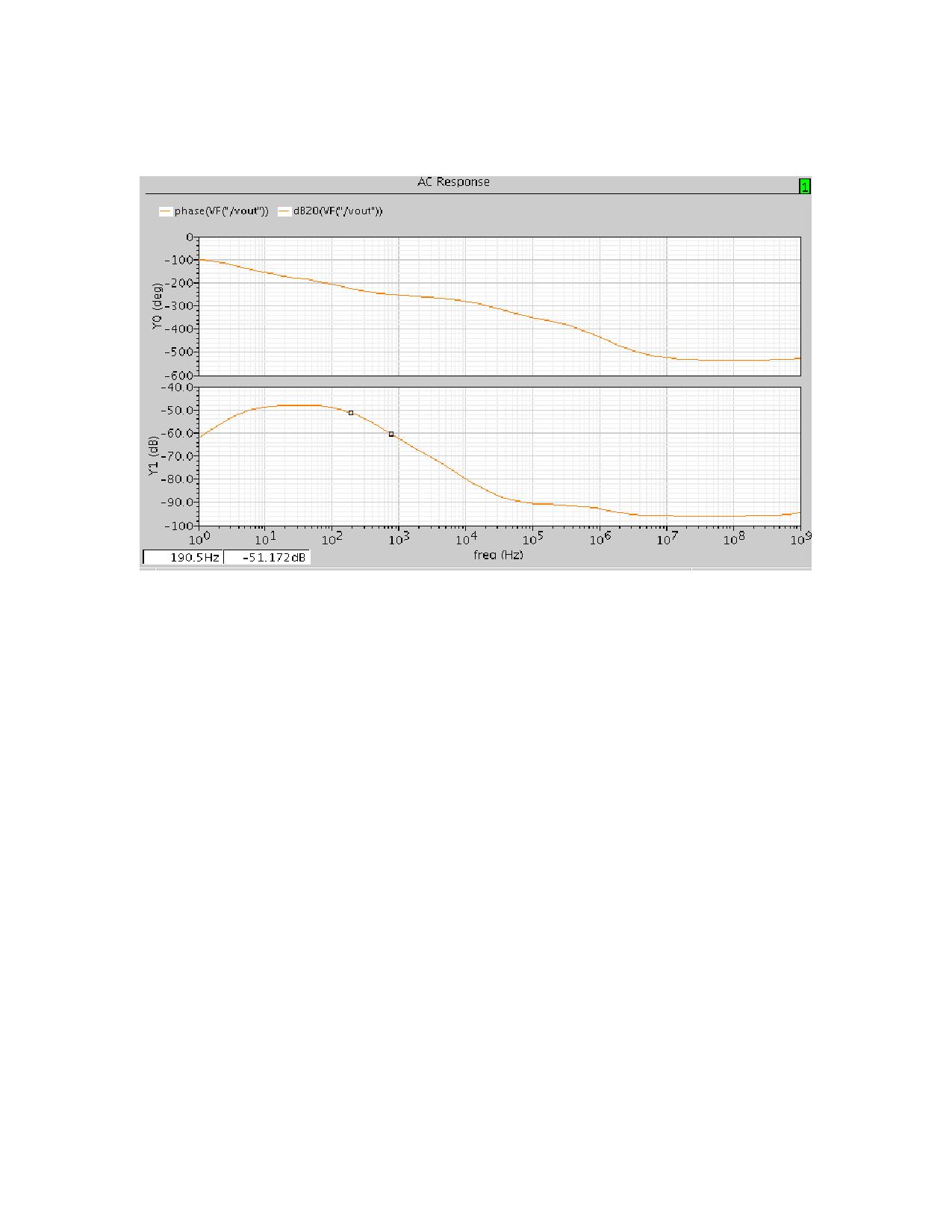
how do you find out if the system is stable or not from the frequency analysis i.e. AC analysis(using cadence spectre)
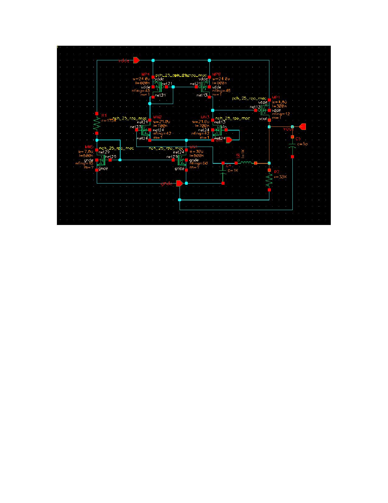
 

Re: stability of a system

look at bode plot for phase and gain

vs frequency

gain margin & phase margin must be suitable for stability
------------------------------------------------------------
 

stability of a system

In a common system, phase margin at unity gain > 60 degree means stable
 

    bharathr87

    Points: 2
    Helpful Answer Positive Rating
Re: stability of a system

Actually not right. Theoretically, the limit for stability is phase margin of 0. Phase margin of 60 and more simply means that the step response will have very little or no ringing. Phase margin of 45 is generally considered as the lower limit for good behavior meaning there is quite a lot of ringing but it can be ok if sin signals are processed. Not so good if pulse signals are considered. In this case better aim at 72 degrees of phase margin.
 

    bharathr87

    Points: 2
    Helpful Answer Positive Rating
Re: stability of a system

thank you for the reply :) these r the gain n phase plots i have got for the buffer amplifier....it is unstable right? wat modifications do i have to for the circuit if i hav to make it stable? the load cap. can be >=3.5pF.


Re: stability of a system

What I see from your circuit is that you try to break the loop by the inductance and the 1K capacitor but you do not inject a signal in the loop. Which makes me think that you apply a signal at the Vin i.e. the + input of the amplifier. This is a wrong way to simulate the stability and what you have in the plots is not the loop gain and respectively you can not judge for the phase margin from there. What you should do is disconnect C4 from ground and put an ac voltage source between this end of C4 and ground. To the Vin apply only DC input voltage with which you work. Measure the ratio of the voltages Vout/V(net23) - this is your loop gain. Well, approximate for high frequencies because you disturb the loading in the loop.
This kind of amplifier is not usually compensated with the output capacitance C5. With the R7=3.3k and C5=5p you get almost 10MHz output pole. The pole at the output of the diff-pair is probably not extremely far from this too. You should better use Miller compensation to achieve pole splitting. Try those things, I think it'll help.
 

Re: stability of a system

hey i went thru miller compensation in Razavi but couldnt understand ....could u tell me how to apply miller compensation for this circuit??
 

Re: stability of a system

U can reference this document
it can show u how to simulate the stability of the circuit in Spectre
 

    bharathr87

    Points: 2
    Helpful Answer Positive Rating
Re: stability of a system

Put a capacitor between the drain and gate of your output PMOS transistor. The value of it you'll have to find by yourself since I don't know the parameters of your circuit. You may also need to cancel the RHP zero by a resistor in series with that capacitor. Try it and post the results.


bharathr87 said:
hey i went thru miller compensation in Razavi but couldnt understand ....could u tell me how to apply miller compensation for this circuit??
 

Re: stability of a system

How to find the value of the cap. to be connected bwn gate and drain of pmos (Cc)? And can i use Rz=(Cl+Cc)/(gmp*Cc)
where Cl is the load cap. and Cc the value of the Miller Compensation cap. who's value i need to find in the first part?
 

Re: stability of a system

The easiest will be to put a capacitor there, sweep it's value and find out for which value you get good phase margin. More appropriate would be to do some analysis, so you know what's happening in the circuit. If Cc is your capacitor between gate and drain of the PMOS device then the equivalent Miller capacitance at the output of the first stage is approximately CM=gmp*R7*Cc. At the output of the 1st stage you have a dominant pole 1/Ro1(C1+CM) where Ro1 is the output resistance of the 1st stage and C1 is the capacitance (not including the Miller one) at that output. The DC gain is gm1*Ro1*gm2*R7. The unity gain frequency is ωo=gm1*gmp*R7/(C1+gmp*R7*Cc)≈gm1/Cc. The approximate result is if you can assume C1<<CM.
The second pole very approximately is 1/[(R7||(1/gmp))*CL]≈gmp/CL if 1/gmp<<R7. More accurately, but still not exact is
[(R7/gmp)/(R7+(1/gmp)*(C1+Cc)/Cc)]*(C1+CL+CL*C1/Cc)
The zero is approximately gmp/Cc.
If you don't have other restrictions like noise for example, choose your second pole to be 3-4 times higher than the unity gain frequency ωo. The RHP zero is good to be about 10x higher than the ωo, but it is difficult to make. That's why put a resistor in series with Cc to move the zero to ∞ or in the LHP close to the second pole, which will kind of cancel it. Be aware though that this cancellation is not a good idea if your circuit is processing pulse or step-like signals where you need good and fast settling. It is ok for sin signals. You can find in books the formula for this resistor or just sweep it's value until you get satisfactory results.
 

    bharathr87

    Points: 2
    Helpful Answer Positive Rating
Status
Not open for further replies.

Part and Inventory Search

Welcome to EDABoard.com

Sponsor

Back
Top