evios
Junior Member level 1
pic wattmeter
I am planning to have this project implemented. But I had not much knowledge on circuits.
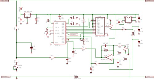
Bigger picture here
Well, 1st of all is the part on the input at RA0 served as the voltage sensor. I am not very sure on why there is a potentiometer located parallely with the 4k7 resistor. Voltage divider concept?
Another part is on the Op-Amp, scales the current up and read to RA1. Pretty bad that the inverting part is too complex to understand.
Can anyone provide me with useful and details on it? Thanks, i really appreciate it.[/url]
I am planning to have this project implemented. But I had not much knowledge on circuits.
Bigger picture here
Well, 1st of all is the part on the input at RA0 served as the voltage sensor. I am not very sure on why there is a potentiometer located parallely with the 4k7 resistor. Voltage divider concept?
Another part is on the Op-Amp, scales the current up and read to RA1. Pretty bad that the inverting part is too complex to understand.
Can anyone provide me with useful and details on it? Thanks, i really appreciate it.[/url]