Continue to Site

Welcome to EDAboard.com

Welcome to our site! EDAboard.com is an international Electronics Discussion Forum focused on EDA software, circuits, schematics, books, theory, papers, asic, pld, 8051, DSP, Network, RF, Analog Design, PCB, Service Manuals... and a whole lot more! To participate you need to register. Registration is free. Click here to register now.

Alias when Fstop > Fs/2 in matlab

Status
Not open for further replies.

cafukarfoo

Full Member level 3
Joined
Jul 25, 2007
Messages
170
Helped
8
Reputation
16
Reaction score
5
Trophy points
1,298
Activity points
2,510
matlab alias

Hello Sir/Madam,

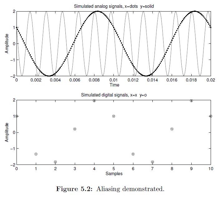
If filter fstop > fs/2, i should see alias.

How can i simulate this alias in matlab? Can anyone give some suggestion here?

Thanks.
 

aliasing matlab code

Do u want to simulate the alising effect and show ,...as in a presentation or somthin lik tat
 

matlab example aliasing

Hi tibm,

Yes. I would like to see the alias effect if we don't design the filter well where the stopband > fs/2.

Do you have any idea? THanks.
 

pi = fs/2

Aliasing Example

The program below demonstrates this problem graphically. We simulate sampling
two sinusoids, 2 cos(2Π100t +Π/3) and 2 cos(2Π600t +Π/3), at 500 samples/second.
They are given the same magnitude and phase for a reason: the program shows that the sampled versions are identical.

%
% Example of aliasing with
% 2 cos(2 pi 100 t + pi/3)
% and 2 cos(2 pi 600 t + pi/3)
%
% if these are sampled at 500 samples/sec,
% then the sampled versions are identical!
%
freq = 100; % example frequency
phase = pi/3; % example phase
mag = 2; % example magnitude
fs = 500; % sampling frequency
Ts = 1/fs; % sampling period
k = 1; % number of repetitions
num_points = 200; % How many points to use
% 200 makes it look smooth
num_samples = 11; % How many samples to simulate reading
% 11 puts "sampled" under "analog"
step = 2/(freq*num_points); % get a nice step size
t = 0:step:2*(1/freq); % "time"
n = 0:num_samples-1; % sample index
% x and y are simulated analog functions
x = mag*cos(2*pi*freq*t + phase);
y = mag*cos(2*pi*(freq+k*fs)*t + phase);
% x2 and y2 are simulated sampled version of x and y
x2(n+1) = mag*cos(2*pi*freq*n*Ts + phase);
y2(n+1) = mag*cos(2*pi*(freq+k*fs)*n*Ts + phase);


Both x2 and y2 have the same values. To show the simulated sampled versions,
the following code plots both, and generates Figure 5.2.

% Plot the "analog" signals
subplot(2,1,1);
plot(t, x, 'r.-', t, y,'b-');
my_title = sprintf('Simulated analog signals, x=dots y=solid');

figure 5.2:


By the way: this is not my own program. I found it in the following book:

Digital Signal Processing using Matlab and Wavelets

By: Michael Weeks ©2007
 

matlab alias signal

Hi Aya2002,

Thanks for your reply.

I think your code is more on demonstrate the concept of alias.

What i am looking forward is a matlab code to show alias happen for filtered signal if the digital filter have Fstop>Fs/2.

Thanks.
 

Status
Not open for further replies.

Similar threads

Part and Inventory Search

Welcome to EDABoard.com

Sponsor

Back
Top