Continue to Site

Welcome to EDAboard.com

Welcome to our site! EDAboard.com is an international Electronics Discussion Forum focused on EDA software, circuits, schematics, books, theory, papers, asic, pld, 8051, DSP, Network, RF, Analog Design, PCB, Service Manuals... and a whole lot more! To participate you need to register. Registration is free. Click here to register now.

How can i excite TE10 waveguide mode using Floquet ports?

Status
Not open for further replies.

harishbigh

Newbie level 4
Joined
Jan 27, 2006
Messages
7
Helped
0
Reputation
0
Reaction score
0
Trophy points
1,281
Activity points
1,340
te 10 mode

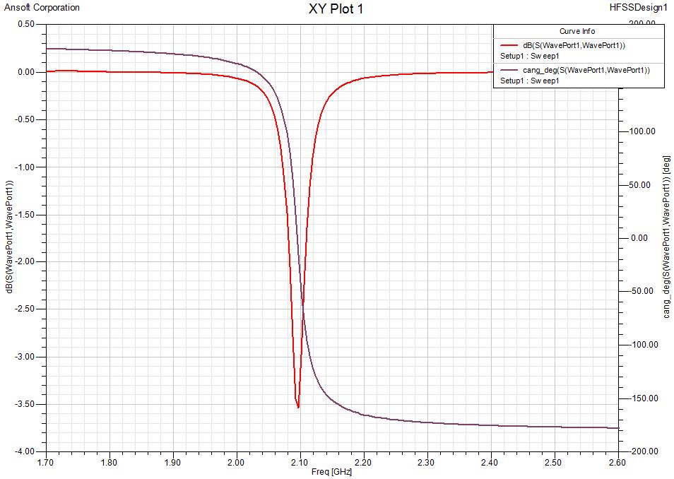
I am trying to calculate reflection phase for patch reflectarray and i want to compute the reflection phase using floquet ports.
I have simulated the reflectarray structure using waveguide simulator approach and already got reflection amplitude and phase.
I am trying to use floquet ports to excite similar TE10 mode and compare my results.

Any suggestion are welcome.

thank you
 

floquet modes

Hi,
first of all draw ur reflectarray unit cell inside an airbox. After that u must apply master/slave boundaries at the lateral faces of the airbox itself, so 2 masters and two slaves if u are using a rectangular lattice. Then, u can assign a floquet port to the airbox face opposite to the reflecting unit cell. Setting the port for such a case require the definition of just two modes, so called fundamental modes in the Floquet expansions. By using such an approach u are considering two possible orthogonal plane waves incident to your unit cell. Lattice vectors for the Floquet port must have a common origin at an arbitrary corner of the face where the port is placed. The first vector, A, must lie on one edge of that face while the vector B must lie on the orthogonal edge of the same face. Once u have defined this situation, just apply the deembedding at the port up to the cell surface. The s11 phase and amplitude is what u are looking for. Consider that u will have 2 S11s, one for the first mode and one for the second orthogonal mode. In order to understand which is the right parameter to be analyzed, visulize the port modes and choose ur desired polarization. And that's it. I hope u can manage to perform ur analysis with these information. Good Luck!

Ivan
 
floquet ports

Dear Ivan
Thank you for your reply.
I have created a model for the reflectarray element.
One: Using parallel plate waveguide to obatin normal incidence
Two: using floquet ports for normal incidence.

I am attaching the file.
please let me know if the confguration is correct as the results that i get dont make sense for the floquet ports. (S11 reflection magnitude and phase)
 

excite parallel plate waveguide

It's useless to put more vacuum beyond the ground plane, so terminate the airbox with the ground plane. There's no radiation beyond it, being an infinite ground plane :). Moreover, you don't get reliable results since the convergence process is absolutely unstable especially for the second model. Moreover, how is the periodicity of your real array? Is it square? If yes, try to use a square unit cell with dimensions equal to the periodicity. I think u used a rectangular arrangement referring to the dimensions of the wavegiode where u performed the measurement. Moreover, by the simulation of the second model, I found a characteristic impedance which is half the free space impedance but it must be a full free space impedance. A thing u can try to do is to use symmetry boundaries with an impedance multiplier equal to 1. If u can, upload the measurement the way I can compare it with the models.

I.
 

    harishbigh

    Points: 2
    Helpful Answer Positive Rating
reflectarray measurement

Thats a good point about terminating the box with ground plane but eventually i want to put a slot in the ground plane and computer S21 so i have the model setup that way.

I tried to simulate the structure using square configuration (actual requirement).
I got some results now for reflection phase using Floquet ports and Parallel plate incidence.
I looked at the characteristic impedance and it shows 377 ohms.

I wasnt sure about your comment on convergence (unstable)? Can you please elaborate?

I will also try to look into symmetric boundaries.

I have uploaded the measurements (it is in the paper).


thank you for your suggestions.
 

waveguide mode

Ok, the Zo is correct. With unstable I meant that the convergence curve during the adaptive process went up and down, while it should have a decreasing trend pass after pass to have reliable results. It depends on the simulation setup, mesh setup, on the geometry, etc.

If u want to get the same results as those shown in the paper, u should use only pec conditions, reproducing the waveguide. Otherwise u won't have a TE10 mode as u require, but floquet modes. In particular u will have the two fundamental modes of the floquet decomposition representing two possible orthogonal plane-waves. But if u want a TE10 mode the situation must be different.
I will have a look at ur model and meas during this week. I'm having so much work to do... I'll let u know soon.

I.
 

te1,0

This is the result I get with a 30mil thick substrate by a rectangular waveguide simulation (only E-boundaries):


Looks closer to measurements!!!

Ivan
 

Re: How can i excite TE10 waveguide mode using Floquet ports

Dear Ivan,

I'm experiencing almost the same problem. I'm simulating periodic metallic structures with CST. I use waveguide port to excite the structure and select periodic boundaries. I couldn't excite TE10 mode, especially when I'm using oblique incidence. It always excite Floquet modes. I don't understand of generating master and slave boundaries.

If possible, would you please post the modified model to this topic?

Thank you very much!
 

Re: How can i excite TE10 waveguide mode using Floquet ports

Dear psycrystal,
at the moment I don´t have CST, I´m waiting for the license... :D Anyway, you can upload your model, maybe I can have a look at it when I´ll have cst available.

Regards,

I.
 

floquet mode using CST be more easy than HFSS
you just choose unit cell boundry condition,and use your floquet mode
it so easy,i already try it
regards
 

Status
Not open for further replies.

Part and Inventory Search

Welcome to EDABoard.com

Sponsor

Back
Top