Continue to Site

Welcome to EDAboard.com

Welcome to our site! EDAboard.com is an international Electronics Discussion Forum focused on EDA software, circuits, schematics, books, theory, papers, asic, pld, 8051, DSP, Network, RF, Analog Design, PCB, Service Manuals... and a whole lot more! To participate you need to register. Registration is free. Click here to register now.

Problem with RC sinus generator...

Status
Not open for further replies.

johnymo

Newbie level 1
Joined
Jan 24, 2009
Messages
1
Helped
0
Reputation
0
Reaction score
0
Trophy points
1,281
Activity points
1,289
sinus generator

Hi, I have got a problem with my sinus generator based ona a Wien schematic and amplifier,that should work between 1Hz and 20kHz, I've tried everything,
I need to get Total Haramonic Disortion <1% and this is my main problem:/
This is my schematic:
20_1232825026.jpg

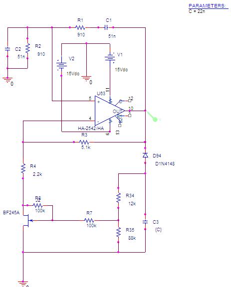
I am designing it in PSpice 9.2,
please help me as You can...
I have attached this project...
best regards
Thank You
 

sinus generator circuit

johnymo said:
Hi, I have got a problem with my sinus generator based ona a Wien schematic and amplifier,that should work between 1Hz and 20kHz, I've tried everything,
I need to get Total Haramonic Disortion <1% and this is my main problem:/

1.) Should the oscillator be tunable between 1Hz and 20 kHz ? This will be very difficult to realize !
2.) Even if tuning is not required, the rectifying circuit has to be redesigned for low, medium and high frequencies because the RC time constant should be at least 20..50 times the oscillation period.
3.) This part of the circuit will contribute to the THD if this requirement (as mentioned above) is not fulfilled.
4.) Another possible source of non-linearity is the FET as the amplitude across drain and source must not exceed (let´s say) 0.5 volts. This peak value should be as low as possible. On the other side, the FET has to control the whole circuit and to settle the amplitude within a certain time. That means, you have to find an optimum compromize. And that´s another argument against tuning over such a broad range.
5.) In summary: Designing an oscillator for different frequencies with tight requirements for THD is a difficult task which requires compromizing.

Added after 19 minutes:

Added 15 minutes later:

For the present design as given in the diagram, gate voltage varies by app. 150 mV !
Clearly, this is the reason for distortions. Increase the rectifier time constant !
As a general hint: Watch the gate voltage during simulation. It should be as constant as possible !!

Added after 3 hours 10 minutes:

Hi Johnymo,

just now I have discovered that you have tried to linearize the FET with R7 and R8.
Remove R8 and increase the rectifying cap by a factor of 5..10 - and you will have a nearly perfect oscillator.
The effect of R7 and R8 is contra-productive if the divider ratio is not carefully calculated including the rectified voltage.
I think, if the voltage across the FET is not larger than 100mV it is not neccessary to linearize the FET.
 

sinusgenerator

I don't think it's a good idea to omit the linearization, although the FET voltage is rather low. Even harmonics are surely higher then. I found, that the circuit can achieve below 0.1% THD according to PSPICE fourier analysis, with linearization and if the rectifier filter is adjusted respectively. There are however several issues with your simulation setup, that prevent a correct measurement of distortions:

1. As you can see from the voltage waveform, the timestep must be much smaller to avoid pseudo distortions from too few waveform samples. 10 or 20 us may be a meaningful starting point.

2. PSPICE fourier analysis option apparently expects an exact fundamental frequency, otherwise distortions from discontinuities at the interval boundary can occur. Try fine tuning of the fourier fundamental towards the actual signal frequency.
 

sinus generator schematics

FvM said:
I don't think it's a good idea to omit the linearization, although the FET voltage is rather low. Even harmonics are surely higher then. I found, that the circuit can achieve below 0.1% THD according to PSPICE fourier analysis, with linearization and if the rectifier filter is adjusted respectively.............
..............

I feel that the improvement of the "linearization" path is not due to a linearization effect (because of the transfer curve of the FET which is already quite linear due to the low DS voltage). Rather, there is an improvement since the contribution of the FET to the whole resistance is smaller because of feedback - and therefore, its contribution to the THD.
This can be prooved by the following experiment:
1.) Remove the 100k feedback resistor between D and G of the FET
2.) Reduce the contribution of the FET resistance by shunting the drain-source path with a 300 ohms resistor (the FET alone has app. 400 ohms)
3.) Correspondingly increase the resistor above the FET from 2.2k to 2,4k.
4.) as a result the THD will be also below 0.1 %

Thus, we have a sinewave at app. 3.4 kHz with THD<0.1% without linearization network. This procedure, of course, could be continued by stepwise reducing the FET contribution to the resistance of the whole path - however, more and more it would become more academic due to tolerance effects.

Sorry, I forgot to mention that the rectifying cap is 500 nF.
 

Status
Not open for further replies.

Similar threads

Part and Inventory Search

Welcome to EDABoard.com

Sponsor

Back
Top