Continue to Site

Welcome to EDAboard.com

Welcome to our site! EDAboard.com is an international Electronics Discussion Forum focused on EDA software, circuits, schematics, books, theory, papers, asic, pld, 8051, DSP, Network, RF, Analog Design, PCB, Service Manuals... and a whole lot more! To participate you need to register. Registration is free. Click here to register now.

Count limiting circuit

Status
Not open for further replies.

ivanljh

Junior Member level 1
Joined
Jan 17, 2009
Messages
16
Helped
0
Reputation
0
Reaction score
0
Trophy points
1,281
Activity points
1,425
count limiting circuit

I am required to build a car that can move forward from Station to Station, reverse automatically and stop after hitting an emergency switch (micro switch) in the forward and reverse direction.

So basically, I’ve completed the following:
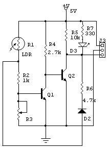
1) Light Dependent Sensor Circuit – to detect the station.
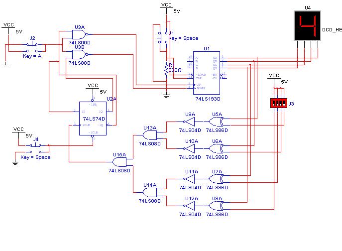
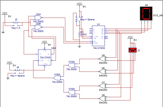
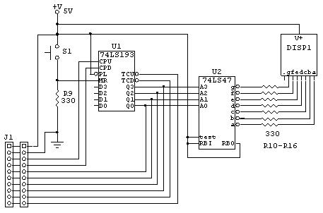
2) Counter & Display Circuit – to display the Station number on the 7-segment LED display.
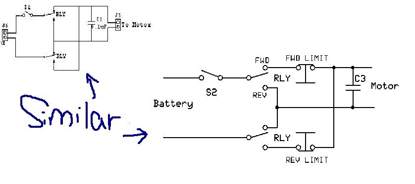
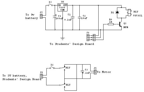
3) Motion Control Circuit – to activate the motor and move the car in forward and reverse direction.
4)Voltage Regulator Circuit – to provide 5V dc supply.

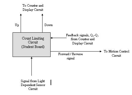
But now, I am having problem in designing a counter limiting circuit that is able to enable, integrate the above circuit and move the car forward to any Station, reverse automatically and stop after hitting an emergency switch (micro switch) in the forward and reverse direction. What should I do?? Need help desperately!
 

theory of the circuit forward-reverse ldr

Can you post your circuit? How you limit the count depends a lot on what technology you used...discrete transistors...TTL?...CMOS...microcontroller?

Ken
 

xnor gate example

KMoffett said:
Can you post your circuit? How you limit the count depends a lot on what technology you used...discrete transistors...TTL?...CMOS...microcontroller?

Ken

Hi... these are the other circuit.

Light Dependent Sensor Circuit

32_1232364097.jpg


Counter and Display Circuit

46_1232364140.jpg


Motion Control Circuit

10_1232364339.jpg


Count Limiting Circuit

65_1232364193.jpg


We are given these ICs to build

1) 74LS32 OR gate
2) 74LS08 AND gate
3) 74LS04 NOT gate
4) 74LS02 NOR gate
5) 74LS00 NAND gate
6) 74LS74 D flip flop
7) 2N3904 NPN transistor
 

d-flip flop counter reverse up/down

For the "emergency" stop function at the end of forward or reverse travel this circuit should work. Once a limit switch is opened, the car will remain stationary until the relay is switched to the opposite direction.

14jampw.jpg
[/img]

Ken
 

design a circuit which count 5 minute count

KMoffett said:
For the "emergency" stop function at the end of forward or reverse travel this circuit should work. Once a limit switch is opened, the car will remain stationary until the relay is switched to the opposite direction.

Hi... I appreciate your help. However, I belive the circuit above already has this function (see: Motion Control Circuit). But I am not sure how the count limiting circuit should look like. (I heard someone is using a D Flip-Flop and a AND gate) Thanks anyway. :)
 

ic 74ls32

However, I belive the circuit above already has this function (see: Motion Control Circuit).

Can you point out how you see this happening in your motor control circuit?

Ken
 

count up and relay on circuit

KMoffett said:
However, I belive the circuit above already has this function (see: Motion Control Circuit).

Can you point out how you see this happening in your motor control circuit?

Ken

Hi. (See attached: Motion Control Circuit 1)
Correct me if Im wrong. Thanks!

Ivan

Motion Control Circuit 1

0_1232378793.jpg
 

rev limiter circuit

The similarity was intentional. What I was adding were the "emergency" microswitches...FWD LIMIT and REV LIMIT...that you referred to in your original posting.

stop after hitting an emergency switch (micro switch) in the forward and reverse direction.

I didn't see that function in any of your schematics. My assumption was that S2 and S3 are just power supply on/off switches.

Ken

Added after 12 minutes:

As for:
...a counter limiting circuit that is able to enable, integrate the above circuit and move the car forward to any Station, reverse automatically...

Since you are "counting stations", may I assume that there are several of them along the car's route? Are you going to have some way to tell the system that the car is to be detected for reversal at a specific numbered station?

Ken
 

circuit to close switch count

KMoffett said:
The similarity was intentional. What I was adding were the "emergency" microswitches...FWD LIMIT and REV LIMIT...that you referred to in your original posting.

stop after hitting an emergency switch (micro switch) in the forward and reverse direction.

I didn't see that function in any of your schematics. My assumption was that S2 and S3 are just power supply on/off switches.

Ken

Added after 12 minutes:

As for:
...a counter limiting circuit that is able to enable, integrate the above circuit and move the car forward to any Station, reverse automatically...

Since you are "counting stations", may I assume that there are several of them along the car's route? Are you going to have some way to tell the system that the car is to be detected for reversal at a specific numbered station?

Ken

Oh I see... Do you have any idea on how the count limiting circuit should look like? I tried searching through the internet but I couldn't find any example.
 

logic digital comparator

A digital comparator can tell you when the selected station number and the displayed station number are the same. This can be implemented with a stack of seven AND gates and 4 switches. When the binary output from the counter in the same as the binary number set with the switches the output of the comparator will go high.

2hx3639.jpg


Ken
 

count limiting circuit for speific station

KMoffett said:
A digital comparator can tell you when the selected station number and the displayed station number are the same. This can be implemented with a stack of seven AND gates and 4 switches. When the binary output from the counter in the same as the binary number set with the switches the output of the comparator will go high.

Ken

Hi Ken… Thanks for the useful information. I really appreciate your help. (To make the car to perform any loop is a bonus) At this moment, I’m required to build a car that is able to count and move from station 1 to station 5 and then reverse using ‘Count Limiting Circuit’. This Count Limiting Circuit is supposed to get the signals from the ‘Light Dependent Sensor Circuit’ and ‘Counter & Display Circuit’. The circuit will then send signal to the Motion Control Circuit to make it move forward/reverse and up/down signal to the ‘counter & display circuit’.

But I am having a problem here. The circuit that I design can’t work! What could be the problem? I think it could be the D flip flop. (See attached: mydesign)

Ivan

mydesign

72_1232541889.jpg
 

counter contol circuit

2hmzm92.jpg


I redrew your sketch in logic format. Easier for me to follow.
Input 0101 is the input is your "5" from the counter?
I don't know what the 3rd input (?) is.
Output (Relay) goes to the relay circuit?
I don't know what outputs (4) and (5) are for.

Can you explain your intended step by step operation?

Ken
 

circuit for counting in reverse order

KMoffett said:
I redrew your sketch in logic format. Easier for me to follow.
Input 0101 is the input is your "5" from the counter?
I don't know what the 3rd input (?) is.
Output (Relay) goes to the relay circuit?
I don't know what outputs (4) and (5) are for.

Can you explain your intended step by step operation?

Ken

Input 0101 is the input is your "5" from the counter?
Yes. That's right.

I don't know what the 3rd input (?) is.
It's the signal from LDR. It is used as an enable signal for the AND gate.

Output (Relay) goes to the relay circuit?
Yes.

I don't know what outputs (4) and (5) are for.
It should be (3) and (4). (3) goes to the 'counter & display circuit' for counting up and (4) is for counting down.

Can you explain your intended step by step operation?
Well… these are just my concept. I don’t know if they’re right or wrong.

1) Q2 and Q0 is connected to the AND gate. So when the counter counts to 0101, the output of the AND gate will produce a ‘1’.

2) So this output will be use as the CLK signal to drive the D Flip Flop. Since, the input D is connected to 5V, the output Q will always be a ‘1’ when the CLK signal is high. According to the operation of a D Flip Flop.

3) Then, the output from Q will be used to activate the relay (to reverse the car) and activate the down counter (4) together with the signal from LDR.

4) Noticed that /Q is connected to the other AND gate which produces the output (3), so under normal operation, only one output i.e. (3) or (4) will be activated.
 

reversing motor circuit using flip-flops

OK. I follow your logic. Now for "The circuit that I design can’t work!"

You've reset the D-FF, (4) is low, (3) has been going high and low with each LDR input, the counter goes up to "5", the D-FF Q goes high, the relay is turned-on reversing direction, (3) stays low, and (4) starts going high and low with each LDR input.

What specifically doesn't work.

Ken
 

KMoffett said:
OK. I follow your logic. Now for "The circuit that I design can’t work!"

You've reset the D-FF, (4) is low, (3) has been going high and low with each LDR input, the counter goes up to "5", the D-FF Q goes high, the relay is turned-on reversing direction, (3) stays low, and (4) starts going high and low with each LDR input.

What specifically doesn't work.

Ken

I tried to construct the circuit using a Digital/ Analog Trainer. The first thing that I tried was to test the counting sequence. By right, the counter is supposed to count to ‘5’ and then reverse its count. But the problem is: “the counter can’t even count up when I connect the designed circuit”. I believe that the problem lies within the design of this Count Limiting Circuit. My design might be wrong.

I am quite sure that there is nothing wrong with the counter and display circuit because at this moment (without the Count Limiting Circuit), the car is able to count up and move forward. The use of the count limiting circuit is for the car to count down and move in the reverse direction.

Ivan
 

Hi,

I am still having a problem with the count limiting circuit… I realize the count can only be displayed properly ONLY when one switch is set to logic ‘1’. i.e. When I have more than one switch being set to logic 1', the circuit can't functiion properly... I can only have mod 2, mod 4, mod 8…(unable to have other mod numbers like 3, 5 & 7) What could be the problem? Thanks

PS: the switch is J3

69_1233335258.jpg
 

Why are you using the XOR with Inverters to compare the DIP switch and the 74LS193 outputs?

The logic output of the XOR + Inverter is:

A B C
0 0 1 True (invalid)
0 1 0
1 0 0
1 1 1 True

You need to use 4 more AND gates, instead of the 4 XOR's and 4 Inverters. So logic output is:

A B C
0 0 0
0 1 0
1 0 0
1 1 1 True

Ken
 

Hi… I thought what we want to achieve is “when the binary output from the counter in the same as the binary number set with the switches the output of the comparator will go high”? So lets say the output at Q0 and SW1 is set to ‘low’, we won’t be able to get a ‘high’ at its output.

76_1233374167.jpg


I've also tried re-implementing the circuit with AND gate replacing XOR+inverter i.e. XNOR. But it's still unable to work properly.
 

#1 - I strongly suggest you tie the IC input to high or low(whatever you want) by using a 1K ohm resistor. i.e.7474 clear input,7400 input and dip switch

#2 - when troubleshooting,a digital probe will help a lot.

#3 - deadline reaching soon, good luck ; )

Added after 1 minutes:

ivanljh said:
Hi… I thought what we want to achieve is “when the binary output from the counter in the same as the binary number set with the switches the output of the comparator will go high”? So lets say the output at Q0 and SW1 is set to ‘low’, we won’t be able to get a ‘high’ at its output.

you are using XNOR gate,when the inputs are the same,output is HIGH.
 

Status
Not open for further replies.

Similar threads

Part and Inventory Search

Welcome to EDABoard.com

Sponsor

Back
Top