Continue to Site

Welcome to EDAboard.com

Welcome to our site! EDAboard.com is an international Electronics Discussion Forum focused on EDA software, circuits, schematics, books, theory, papers, asic, pld, 8051, DSP, Network, RF, Analog Design, PCB, Service Manuals... and a whole lot more! To participate you need to register. Registration is free. Click here to register now.

Question about dB values in Gaussian filter for a RF receiver

Status
Not open for further replies.

M.B.

Member level 2
Joined
Mar 31, 2008
Messages
47
Helped
2
Reputation
4
Reaction score
2
Trophy points
1,288
Location
TUNISIA
Activity points
1,561
gauss filter

Hi to all,

I am working on GAUSSIAN filters (Continous Filters) for a RF receiver.
This filter is a Low Pass Filter to 12dB. My problem is to know the meaning of the 12dB: What does it refer to?

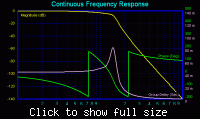
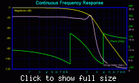
Another point: Can any one comment this two figures and tell me how to calculate the 6dB transition for the first figure and 15dB for the second one.


Thanks in advance
 

gaussian filter

M.B. said:
Hi to all,

I am working on GAUSSIAN filters (Continous Filters) for a RF receiver.
This filter is a Low Pass Filter to 12dB. My problem is to know the meaning of the 12dB: What does it refer to?
Another point: Can any one comment this two figures and tell me how to calculate the 6dB transition for the first figure and 15dB for the second one.

Something I don´t understand is the following:
You are using some phrases like "low pass filter to 12 dB" or "6 dB transition" or "12 dB transition" - and at the same time you are asking what the meaning is of your own words ?

Another point: Obviously, both pictures originate from a filter design program.
But this program needs inputs: filter order, approximation, corner frequency, damping requirements,....

What did you require from this filter ? I suppose this will answer your question.
 

gaussian filter design

Hi M.B.

In the mean time I had the opportunity to look into the filter design program you have used - and I have seen that several transition parameters can be selected for the Gauss approximation without any further explanation.
Therefore, I think this parameter "transition" deserves some comments.
In general, the Gauss filter response has a selectivity which is rather poor - if compared with other approximations. However, it´s time behaviour is rather good since there are absolutely no overshoots for pulsed signals (nearly constant group delay)

1.) The Gauss low pass approximation is based on the exponential function and, therefore, cannot be realized with a finite number of lumped elements.
2.) Therefore, it is approximated by developping it into a mathematical series.
3.) In this context, several methods and modifications are possible leading to a variety of similar functions.
4.) The difference between these alternatives is the "transition band" which is between the pass band and the stop band of the filter.
5.) Example: Transition 12 dB means, that the transition region begins at the corner frequency (normally 3 dB) and ends at 12 dB below the gain at 0 Hz. For attenuation >12 dB the filter curve has a steep roll-off.
6.) It is interesting and important to realize that at the frequency for transition end (example: 12 db) the group delay shows a remarkable peak.

Hope this clarifies something.
Regards LvW
 

design gaussian filter

Hi LvW,

*First, thanks for your reply and sorry for this delay.
*Second, The pictures are obtained from Net, and my target from this pictures is how to compute the transition of a filter.
*Third, the specifiction of my project requires to design a seventh order Low Pass Gaussian Filter to 12dB with a cut frequency equals to 1920Hz. Therefore, I don't understand the meaning of 12dB, it is really the value of the transition or other meaning?
Other thing, this filter is based on Gm-C cells. You can see the following pictures.


If you have any comment or document concerning this type of filter, it will be WELCOME.
Thanks in advance.
 

gauss to 12 db

M.B. said:
Hi LvW,
.......The pictures are obtained from Net, and my target from this pictures is how to compute the transition of a filter.
*Third, the specifiction of my project requires to design a seventh order Low Pass Gaussian Filter to 12dB with a cut frequency equals to 1920Hz. Therefore, I don't understand the meaning of 12dB, it is really the value of the transition or other meaning?

Ok, 7th order low pass with a corner at fc=1.92 kHz. Now, you have for a GAUSS response several alternatives - based on various transition properties.
This means in your case: Between the fc (with -3dB) and the frequency (I call it f12) for which the magnitude is 12 dB down the filter response will go relatively slowly down. Normally, one is interested that the attenuation above fc rapidly increases, but in this case the opposite is true: rather light increase of attenuation between the -3 dB and the -12 dB points. That is the meaning of "transition band of 12 dB". The reason for such a behaviour: constant group delay until app. f12.!
I cannot say how to compute such a filter as its use is very seldom.
But I can give you the following hint: There is a filter design program (Filter-light from NUHERTZ.com) which is capable to compute the pole distribution for your filter.
Having the poles and the transfer function for your circuit you can, in principle, design the filter - however, I am afraid it will be a hard work.
The mentioned program even can design a filter circuitry - based on opamps !
But you are going to use an OTA structure.
Good luck.

Added after 1 hours 28 minutes:

Hi M.B.

I have another message to you.
There is a filter design program FILTERPRO which can be downloaded for free from ti.com .
This program allows a GAUSS -12dB-response and gives you a lot of additional information (pole frequencies, pole Q, circuits with parts values for opamp cascade design).
Regards
 

    M.B.

    Points: 2
    Helpful Answer Positive Rating
gaussian filter attenuation

Hi LvW,

Thanks for your reply.
Now, I use the FilterPro from TI, it is very interested.
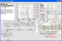
The following picture shows a Gaussian filter to 12dB with fc=1920Hz.


Best Regards
 

Status
Not open for further replies.

Part and Inventory Search

Welcome to EDABoard.com

Sponsor

Back
Top