Continue to Site

Welcome to EDAboard.com

Welcome to our site! EDAboard.com is an international Electronics Discussion Forum focused on EDA software, circuits, schematics, books, theory, papers, asic, pld, 8051, DSP, Network, RF, Analog Design, PCB, Service Manuals... and a whole lot more! To participate you need to register. Registration is free. Click here to register now.

A Question About SC Integrators

Status
Not open for further replies.

naalald

Full Member level 4
Joined
Dec 2, 2006
Messages
216
Helped
30
Reputation
54
Reaction score
5
Trophy points
1,298
Activity points
2,627
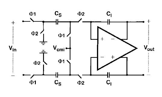
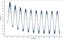
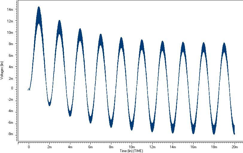
The figure below is the differential output of a switched-capacitor integrator. The input is a 1 mV sine wave: 1m×sinωt. Theoretically the output should be 16m×(1 - cosωt) but it is 16m×(0.5 - cosωt) i.e. it has a 8 mV negative offset and I don't know why? The sampling frequency is 62.5 KHz and the integrator structure is the conventional one.


What's wrong in my simulation? Any suggestions?
 

There are three basic alternatives to design an SC integrator (EULER forward/backward and bilinear). What kind of circuitry do you use ?
 

Hi LvW,
Thanks for your reply. The integrator circuit is a conventional one like this:

Could you please explain what are these structures and that this circuit is which one?
Thanks.
 

naalald said:
Hi LvW,
Thanks for your reply. The integrator circuit is a conventional one like this:
Could you please explain what are these structures and that this circuit is which one?
Thanks.

It´s a symmetrical non-inverting integrator based on the EULER-forward approximation.
 

so cs/ci=16? but it seems at 90degrees phase shift u should get 11.3mv amplitude instead of 8mv?
 

Status
Not open for further replies.

Similar threads

Part and Inventory Search

Welcome to EDABoard.com

Sponsor

Back
Top