Welcome to our site! EDAboard.com is an international Electronics Discussion Forum focused on EDA software, circuits, schematics, books, theory, papers, asic, pld, 8051, DSP, Network, RF, Analog Design, PCB, Service Manuals... and a whole lot more! To participate you need to register. Registration is free. Click here to register now.
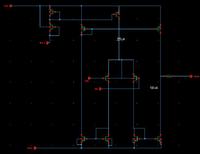
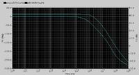
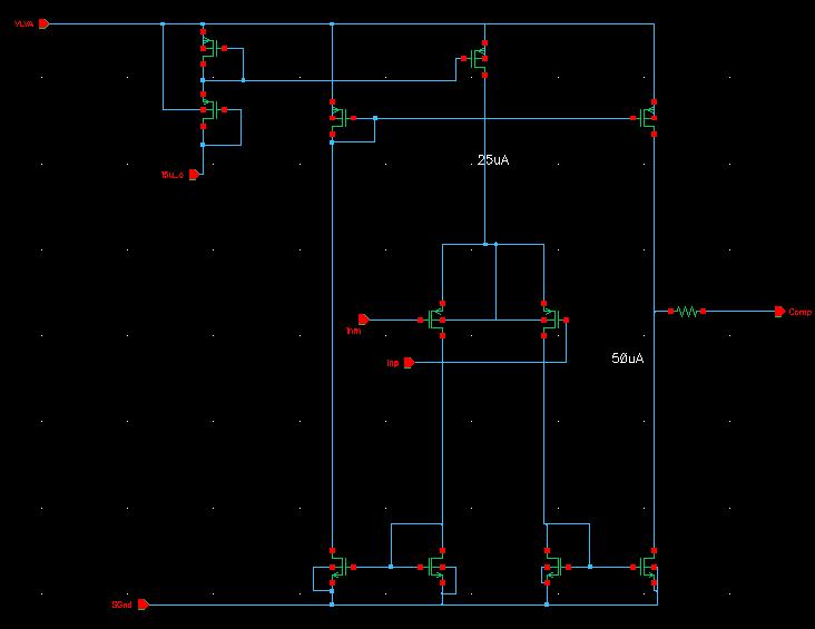
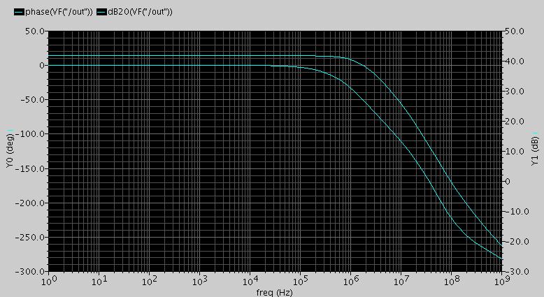
as the pic shown below , it is gm amplifier, why the simulation show magnitude is one pole , but the phase is two pole, and where is the pole on schematic ?It is wierd!
please help!
you have 3 poles and one zero. The dominant pole is at the output - the only high impedance point in the circuit. The other pole is associated with the NMOS current mirrors and the third one with the PMOS current mirrors. The zero comes from the fact that the signal sees unequal paths to the input. One path is shorter - through one of the NMOS mirrors, directly to the output. The other path is longer, through the other NMOS current mirror and the PMOS current mirror to the output. This last one starts rolling off earlier than the first one, so there is a zero.
This site uses cookies to help personalise content, tailor your experience and to keep you logged in if you register.
By continuing to use this site, you are consenting to our use of cookies.