umery2k75
Advanced Member level 1
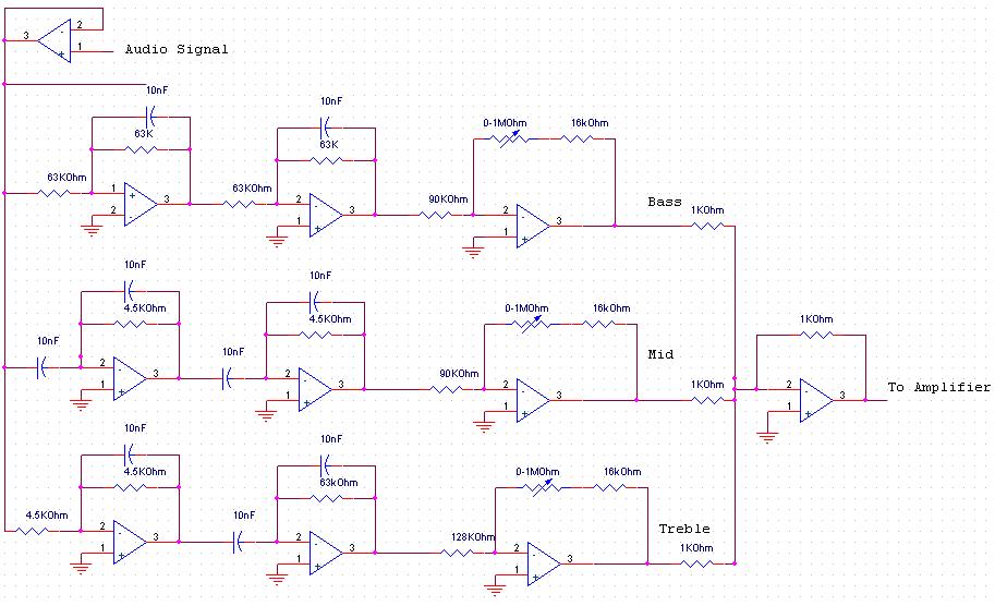
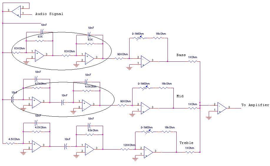
I don't know if this is a good design or not.Circle Op-amp are 2nd order low/high pass filter.
Low pass filter range is 20-250Hz
High pass filter range is 3.5Khz-20Khz
So this is a band pass filter, I think this kind of circuits are known as Speech Filter. I think this circuit is wrong. This circuit was given to me for inspection, by a student, his teacher said your circuit is OK.Now he is asking me, if this is correct. I think this circuit isn't correct. Because this circuit only passes the frequencies from 20-20Khz. So this is kind of a speech filter, but in this circuit, there are gains for Bass,Mid and Treble.I know BASS frequencies are low. I have seen Cars with Woofers fitted in them, which rocks up the floor, as they are low in frequency and treble is for high frequencies, if I'm not wrong. The last stages are gain of them. For the amplifier, the speaker would be just a small 8-16Ohm speaker driven by 386.

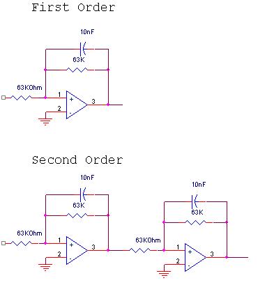
Is this true also, below circuit is low pass filter of 1st order, if we cascade the same filter again, will this become low pass filter of 2nd order. If we keep on cascading same stages, will the order become higher and higher?
Low pass filter range is 20-250Hz
High pass filter range is 3.5Khz-20Khz
So this is a band pass filter, I think this kind of circuits are known as Speech Filter. I think this circuit is wrong. This circuit was given to me for inspection, by a student, his teacher said your circuit is OK.Now he is asking me, if this is correct. I think this circuit isn't correct. Because this circuit only passes the frequencies from 20-20Khz. So this is kind of a speech filter, but in this circuit, there are gains for Bass,Mid and Treble.I know BASS frequencies are low. I have seen Cars with Woofers fitted in them, which rocks up the floor, as they are low in frequency and treble is for high frequencies, if I'm not wrong. The last stages are gain of them. For the amplifier, the speaker would be just a small 8-16Ohm speaker driven by 386.
Is this true also, below circuit is low pass filter of 1st order, if we cascade the same filter again, will this become low pass filter of 2nd order. If we keep on cascading same stages, will the order become higher and higher?