stringskipper
Newbie level 5
Hi everebody! First of all i need to apologize on my english, it's not very good
and if i make some mistakes i hope you will understand it
I'm interested on some ideas about this project.
(all solutions and diferences among them)
I have allready started this and i have some problems.
The basic idea is to create audio amplifier which amplifies
all audible frequencies, and add some circuit which will
amplify bass frequencies. (few decibels). All with op-amps.
So, the (ideal) amplitude characteristic will look like this -->(picture 1)
(gain in bass range must be adjustable)
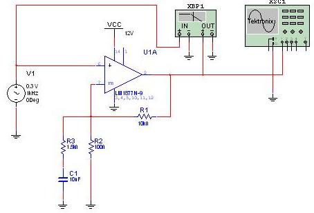
I have create this circuit --> (picture 2, this is
just one block, not stereo),
but this don't work properly! I tried to place filter
circuit in other part of feedback (parallel with R1, of course
with changed values for R-C), but
still it's the same result...--- no bass frequency change!
I'm using LM1877.
(I put these values just for the testing, so the critical
frequency is set to 1 KHz. In real circuit i need to
amplify frequencies from 30 Hz to 170 Hz, without loss of
high frequencies and overall volume).
What solution do you have about this theme, and how can i built this circuit.
I'm very grateful on all answers, ideas and explanations.
and if i make some mistakes i hope you will understand it
I'm interested on some ideas about this project.
(all solutions and diferences among them)
I have allready started this and i have some problems.
The basic idea is to create audio amplifier which amplifies
all audible frequencies, and add some circuit which will
amplify bass frequencies. (few decibels). All with op-amps.
So, the (ideal) amplitude characteristic will look like this -->(picture 1)
(gain in bass range must be adjustable)
I have create this circuit --> (picture 2, this is
just one block, not stereo),
but this don't work properly! I tried to place filter
circuit in other part of feedback (parallel with R1, of course
with changed values for R-C), but
still it's the same result...--- no bass frequency change!
I'm using LM1877.
(I put these values just for the testing, so the critical
frequency is set to 1 KHz. In real circuit i need to
amplify frequencies from 30 Hz to 170 Hz, without loss of
high frequencies and overall volume).
What solution do you have about this theme, and how can i built this circuit.
I'm very grateful on all answers, ideas and explanations.