layers
Newbie level 1
cirucit for uc3524
I need help designing a DC-DC converter circuit based on IC UC3524.
SPECIFICATIONS:
•Power supply to the circuit = 10V DC.
•The output of the circuit should be PWM (Pulse width modulated) waveform.
•The chopper frequency = 2-4kHz ±15%.
•The duty cycle should be manually variable from 0 to 100%.
•There circuit should have emergent stop function.
•The block diagram of the circuit is shown in Figure 1.
•The PWM waveform is shown in Figure 2.
- Use 3 LEDs to indicate the operation state:- Green= Power on
- Red = Load on Motor in Operation
- Yellow= In Emergent Stop
DESIGN CONSIDERATIONS:
•The circuit should be designed using UC3524 to obtain the specified frequency and variable duty cycle.
•A MOSFET is used as the switch as shown in Figure 1 and the waveform as in Figure 2.
•After successful testing on resistive load, the circuit is then used to drive a DC motor and realize variable speed control.
-As the output voltage is of the PWM form,a D Flip-flop is used to keep the RED LED at contant brightness
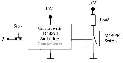
Figure 1. Block diagram of the circuit to be designed
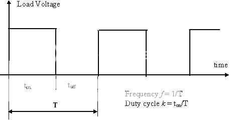
Figure 2. PWM output waveform
thankls in advance
I need help designing a DC-DC converter circuit based on IC UC3524.
SPECIFICATIONS:
•Power supply to the circuit = 10V DC.
•The output of the circuit should be PWM (Pulse width modulated) waveform.
•The chopper frequency = 2-4kHz ±15%.
•The duty cycle should be manually variable from 0 to 100%.
•There circuit should have emergent stop function.
•The block diagram of the circuit is shown in Figure 1.
•The PWM waveform is shown in Figure 2.
- Use 3 LEDs to indicate the operation state:- Green= Power on
- Red = Load on Motor in Operation
- Yellow= In Emergent Stop
DESIGN CONSIDERATIONS:
•The circuit should be designed using UC3524 to obtain the specified frequency and variable duty cycle.
•A MOSFET is used as the switch as shown in Figure 1 and the waveform as in Figure 2.
•After successful testing on resistive load, the circuit is then used to drive a DC motor and realize variable speed control.
-As the output voltage is of the PWM form,a D Flip-flop is used to keep the RED LED at contant brightness
Figure 1. Block diagram of the circuit to be designed
Figure 2. PWM output waveform
thankls in advance