Continue to Site

Welcome to EDAboard.com

Welcome to our site! EDAboard.com is an international Electronics Discussion Forum focused on EDA software, circuits, schematics, books, theory, papers, asic, pld, 8051, DSP, Network, RF, Analog Design, PCB, Service Manuals... and a whole lot more! To participate you need to register. Registration is free. Click here to register now.

Logic Gate Transistor Question

Status
Not open for further replies.

sh3rmy

Newbie level 2
Joined
Apr 3, 2008
Messages
2
Helped
0
Reputation
0
Reaction score
0
Trophy points
1,281
Activity points
1,302
logic gates transistors

I am just learning about electronics and i understand how transistors work but I am having trouble with the math side of things. I am studying the single transistor inverter (which I have drawn very poorly below).

If i have a datasheet for the transistor i wish to use, what information do i need, and how do i use it, to work out what resistors I need?

60_1207189062.png


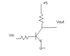
I was told to use a 10kohm resistor on the base, and a 100ohm resistor on the collector, but why? no one can seem to explain it to me. Can anyone help me?

Thanks muchly,
Michael
 

logic gate transistor

The transistor parameter most useful is beta. You need enough base current so that beta times this flows in the collector and the collector resistor is large enough to drop all of Vcc at this collector current.

Then to increase switching speed you need to go beyond this and have a "over drive" effect by sizing the resistors so that there is an excess of collector current. This will make the fall time faster. This cannot be overdone because the stored excess charge will make the rise time slower.
 

    sh3rmy

    Points: 2
    Helpful Answer Positive Rating
transistors maximum load current

I think you should look at Digital Electronics Demistyfied:

as well as Digital Design Principles and Practices:

Added after 2 minutes:
 

    sh3rmy

    Points: 2
    Helpful Answer Positive Rating
transistor switching logic high

Thanks for your help. Been most helpful. :)

Thanks again,
Michael
 

choosing transistor switches?

Hi Phart,
Beta is used for a linear amplifier transistor. Switching transistor circuits use the "max saturation voltage" rating for a transistor where the base current is 1/10th the collector current, even if the beta is very high.

Many transistors have theur beta spec'd with a Vce of 10V, far from saturation.
 

logic circuit and transistor switch

Check for the beta (hfe), VCEsaturation, Max Ic (colector current), VBE.
In a simple example:

Your transistor is a common NPN with max 100mA max Ic, 0.5 Vcesat at 20mA Ic, a 0.7V Vbe and beta of 100 minimum and 400 max.

If you want to provide 20mA to output, the Ib min should be: 20mA/100 = 0.2mA.
This leads to Rb (base resistor) calculation: (Vin - 0.7)/0.2mA. Lets say that Vin is 2.4V minimun high logic level, so Rb = (2.4 - 0.7)/0.0002 = 8500 ohms

Rc can be calculated as: (Vcc - Vcesat) / 20mA = (4.5) / 20mA = 225 ohms

Rc will limit the output current. Rb will limit the base current. See that Vcesat is the output level for Low logic level.

If your input voltage is 0.8 V (low logic level), the output will be:
Ib = (0.8 - 0.7)/8500 = 12uA
Ic = 12uA x 400 (worst case) = 4.8mA (the transistor will conduct a little current, not cut)
Vrc = 4.8mA x 225 = 1.08V
Vc = Vcc - Vrc = 5 - 1.08V = 3.9V (guaranteed output high logic level voltage)

You should make calculations for extreme input voltages for each logic level and use the max and min transistor specs to obtain the output voltages for desired output logic levels.
 

transistor current limit 20ma

rkodaira said:
If you want to provide 20mA to output, the Ib min should be: 20mA/100 = 0.2mA.
No.
Then it might not saturate. The hFE is used when it is a non-saturating linear amplifier with plenty of Vce. The base current should be Ic/10 for it to saturate well.
 

transistor switch logic

No.
Then it might not saturate. The hFE is used when it is a non-saturating linear amplifier with plenty of Vce. The base current should be Ic/10 for it to saturate well.

But if we consider that Ib should be 20mA/10 = 2mA, almost all TTL logic gates outputs will not be able to provide current to this inverter to make it saturate.

See that my example is fictitious and shows what are the kind of calculations need to be done. It does not matter if the transistor operates cut or saturated (as a switch) or in linear mode (amplifier), I was concerned in finding the correct voltage levels and how things are working. For a more correct approach you should consider the input signal source, the transistor power, etc etc.
The correct calculation and the choose of the suitable components will determine the correct point of operation of the logic inverter.
 

logic gates output questions

Does anybody use old TTL anymore?
It sinks at least 16mA but it sources very little and its high output voltage is only about 3.2V.

How about a Cmos logic circuit with a 5V supply? Its minimum output current is only 1mA.

If you want transistors to saturate then give them enough base current for them all to saturate. Or only some of your transistors will saturate.
 

calculate base resistor transistor

Hi,


The procedure below explains how to choose a suitable switching transistor.
NPN transistor switch
(load is on when IC output is high)


Using units in calculations
Remember to use V, A and ohm or
V, mA and kohm. For more details
please see the Ohm's Law page.

1. The transistor's maximum collector current Ic(max) must be greater than the load current Ic.
load current Ic = supply voltage Vs
load resistance RL
2. The transistor's minimum current gain hFE(min) must be at least five times the load current Ic divided by the maximum output current from the IC.
hFE(min) > 5 × load current Ic
max. IC current
3. Choose a transistor which meets these requirements and make a note of its properties: Ic(max) and hFE(min).
There is a table showing technical data for some popular transistors on the transistors page.

4. Calculate an approximate value for the base resistor:
RB = Vc × hFE where Vc = IC supply voltage
(in a simple circuit with one supply this is Vs)
5 × Ic

For a simple circuit where the IC and the load share the same power supply (Vc = Vs) you may prefer to use: RB = 0.2 × RL × hFE

Then choose the nearest standard value for the base resistor.

5. Finally, remember that if the load is a motor or relay coil a protection diode is required

Example
The output from a 4000 series CMOS IC is required to operate a relay with a 100ohm coil.
The supply voltage is 6V for both the IC and load. The IC can supply a maximum current of 5mA.

1. Load current = Vs/RL = 6/100 = 0.06A = 60mA, so transistor must have Ic(max) > 60mA.
2. The maximum current from the IC is 5mA, so transistor must have hFE(min) > 60 (5 × 60mA/5mA).
3. Choose general purpose low power transistor BC182 with Ic(max) = 100mA and hFE(min) = 100.
4. RB = 0.2 × RL × hFE = 0.2 × 100 × 100 = 2000ohm. so choose RB = 1k8 or 2k2.

I hope you understood
5. The relay coil requires a protection diode.
 

inverter logic gate transistor

Hi. Output resistance depend to the desired output resistance which typically is low. base resistor should be low enough to completely switch transistor. it must be lower than (Vcc/Rout/Beta) (for example 2 times lower than).
 

Status
Not open for further replies.

Similar threads

Part and Inventory Search

Welcome to EDABoard.com

Sponsor

Back
Top