lhlbluesky
Banned
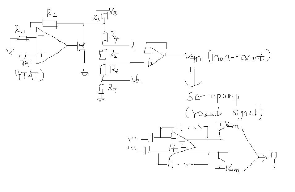
i have designed a voltage divider circuit with a buffer and a resistor divider,
the input is from the PTAT(about 1.24V),when the generated reference voltage Vcm
(0.9V)is connected to the actual circuit(a pipelined adc in sample phase),the value of Vcm changes a little(about 16mV),so the circuit can't work properly;
later i find that the current in the resistor above and below Vcm node is different,
the lower end is larger,the current of the upper end is 0.7uA,and the lower end is 1.5uA;i think the difference comes from the output of the main opamp,why?
how to solve it?