Continue to Site

Welcome to EDAboard.com

Welcome to our site! EDAboard.com is an international Electronics Discussion Forum focused on EDA software, circuits, schematics, books, theory, papers, asic, pld, 8051, DSP, Network, RF, Analog Design, PCB, Service Manuals... and a whole lot more! To participate you need to register. Registration is free. Click here to register now.

How to convert Sinewave to sqr wave from ADC samples?

Status
Not open for further replies.

xtcx

Advanced Member level 1
Joined
Dec 22, 2007
Messages
493
Helped
65
Reputation
130
Reaction score
58
Trophy points
1,308
Location
Bangalore, India
Activity points
5,003
adc covert sine wave to square wave form

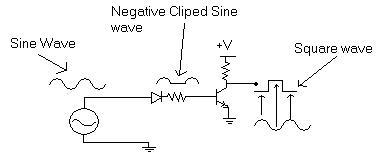
Hi friends!, I need to convert the sine wave of a constant or variable frequency usually at the order of few MHz into a square wave so that I can process the frequency information in that square wave very easily.My config is
ADC of 12-bit which gives over x"4000" samples in total with 0 to 2000 in negative quadrant and 2000 to 4000 in positive quadrant. So I use to check for the incoming data stream from ADC for values above 2000 for '1's and below 2000 for '0's. In this regard I use to convert the sine to sqr. This is very simple in VHDL but there are some duty cycle problems in this approach. I can't make exact decision on this value. Coz there are only 20 samples in the sine wave(I transmit only 20). So the quantization can't be always assured to give same voltage points.....So locking the data seems unpredictable..Is there any way to convert a sine wave into sqr using some other techniques?..thanks
 

convert sine wave to digital

Hello,

I already introduced the PLL point. It would be an adequate solution for optimal SNR performance, but it must not be necessary, so I don't talk of it further. If you are dealing with nearly ideal sine waves, anything is very easy. I don't see a need to have ideal 50 % duty cycle for FSK decoding in your case, so simple sign function should be an appropriate squarewave former. But you should use a highpass filter to remove ADC DC offset before square wave generation. Also a lowpass filter (either anlog or digital) could be a means to reduce noise and restore sine wave shape.

Regards,
Frank
 

fpga convert sine wave to square wave

How about this circuit?.It will convert sine wave into square wave, but this one gives inverted output.If you use the lower end of sine wave generator for biasing the BJT, you will get the in-phase square wave of the sine wave.

92_1202826289.jpg
 

    xtcx

    Points: 2
    Helpful Answer Positive Rating
convert sine signal to square waveform using bjt

FvM said:
I don't see a need to have ideal 50 % duty cycle for FSK decoding
It was like I got the sqr wave with 70% duty cycle. When I used those results for decoding the data as 1s and 0s, the ON time '1' of data is not at equal interval of OFF time '0' after I recover the data from the square wave....I think maintaining the duty cycle within acceptable limits is necessary....Any suggestions?...I'll try to come up with a new idea sooner...
 

convert sine to square wave using bjt

Hello,

70 % duty cycle is surely not due to sine wave distortion, but to DC offset. DC offset should be removed by highpass, as I suggested.

Regards,
Frank
 

circuit to convert sinewave to square wave

but to DC offset. DC offset should be removed by highpass, as I suggested.

i agree with this ,

signal may have some dc level.

why not use comparator module here ?

or subtract ?
 

Ok thanks!, let me see to it and post the results.....

Added after 23 minutes:

Hello,
I confess,I have elaborated my problem in an ambiguous way.My ADC is Bipolar with +\- 2V range. So I guess DC OFFSET is not an issue here, am I correct?..The problem here is that the signals which I recieve in ADC will only have 20/10 different samples for 2MHz/4MHz freq. From that minimum samples, how could I detect the Zero crossing and +ve cycle and -Ve cycle?...I'm not able to exactly detect the zero crossing time of sine wave from the ADC data. Since I get only 20 different voltage levels, it's hard to fix my rising and falling time depending on the sine wave.....Hence the change in duty cyle occurs....I believe..Any solutions to improve coding?.

Added after 5 minutes:

umery2k75 said:
How about this circuit?.It will convert sine wave into square wave, but this one gives inverted output.If you use the lower end of sine wave generator for biasing the BJT, you will get the in-phase square wave of the sine wave.

92_1202826289.jpg
That was one cool circuit which i designed myself and tested for. This is helpful analog design point of view.Thanks "Umery2k75". Unfortunatly here I'm supposed to strict within FPGA. I cannot add any biasing components to it.So I cannot use FPGA for this transistor operation....Anyhow your circuit was really helpful for analog designs.If you have any digital based solutions through coding, do suggest here..Thanks..
 

It's so easy in FPGA. Use a digital comparator. Assume you have a 8 bit linear unsigned sample. You should compare it with a number. typicaly it sholud be 128=2^8/2 for getting a 50% square wave) if you need 70% square waveform you should comapre with a number abou 190. if it's higer set 1 else set 0.

If your waveform is not a good sin, you can use a low pass filter it's equal that an averaging filter. Use three or more cascade 8 bit register and get an average from it. I prefer to use 2 or 4 cascade register depending on how it's noisy. and then feed them to above comparator.

Also you can use a schmith trigger scheme with two level detection. If you have a question feel free to contact me.
 

Thanks "ZEROX100", I as the last part of my test since before I lost hope tried comparing the input data with half of the value for eg, my adc gives 4096 Samples since it's 12-bit adc. So I compared the values in HEX as "FFF" as the max peak for (+ve) and "000" as the max peak for (-ve). So I chose x"500" as the midpoint and coded like this
Process(clk,adc_data)
begin

IF rising_egde(clk) then
if(adc_data >=x"500") THEN
fsk_dem <= '1';
else
fsk_dem <= '0';
end if;
end if;

Ideally as per the code operation, the output should give us the positive quadrant of sine as "ON" time and -ve quadrant of sine as "OFF" time. But in real time since the samples are really as low as 20~10,and high freq of sine as 2&4MHz,there seems to be a problem.the value obtained from sine doesn't seem to be constant. I'm not able to chop the waveform into 2 as sqr.If you have any solution,you may suggest me...Anyway thanks
 

Dear,

May be it's because of your synchronous nature of design. I have another idea: if your sine wave has good quality use a asynchronous nature. Only ompare it with 0x500


if(adc_data >=x"500") THEN
fsk_dem <= '1';
else
fsk_dem <= '0';
end if;

If it's not a good sine wave use an averager as i said. It would filter the noise and aslo high frequncy unwanted harmonies. Anyawy if it's a very bad signal after filtering and doing anything it's impossible to get a fine 50% square wave. If it's your situation, try to use a schmitt trigger. It's will help you to get a better square wave but still not fine. For example you can compare signal with 0x600 to set on and 0x400 to set off. If it's not good for you try to other values. It's just like a game, then you should play with numbers.
If you have another problem let me know and feel free to write me!

I have a question about your area! I'm looking for a job opportunity. i would be pleased, If you help me to find a vacancy.

Regards,
 

Hi xtcx, From your previous messages, it sounds like your FPGA receives a digitized sinewave (varying between 2 and 4 MHz) from an ADC that's sampling around 50 MHz. It would help the discussion if you could clarify what you are building, or which characteristic of the sinewave you are trying to measure.
 

Good question, indeed. I had known from previous threads related to the project, it's a serial topic. It has been said, that the problem is FSK demodulation, the sample rate is 40 MHz, I think. As I already mentioned this may be trivial with pure sine wave or go to the technical limits with minimum SNR.

P.S.: Even with pure sine wave, that could be demodulated "trivially" by a comparator, one should at least make it symmetrical, rather than setting the threshold to 0x500 and complaining about the duty cycle...
 

Hello Friends!
Sorry my connection from server was down for a day. ok I'm doing a project on SDR. The idea about developing is all by mine(it's just a prototype).I have the following peripherals in my Mainboard.
1) Xilinx Virtex 4 FPGA
2) Adjustable master clock from 1 MHZ to 100MHz.
3) 40MHz ADC/125MHz Dac*
4) Codec(2 ch)**
5) XILINX ISE 8.2i, Modelsim6
* ADC\DAC has it's own filter circuits. It's bipolar device,have range 2Vpp
**Codec again has filter circuits built around it. So codec offset error can be rejected

In my project(On FPGA only) there are different layers of operations inside FPGA
Layer 1 :- DATA from Codec @ 2MHz bit rate contains 16 Lch + 16 Rch(32bits)
Layer 2 :- Adding header,marker,checksum(CRC)
Layer 3 :- CODING (Manchester,NRZ,8b\10b,etc if any)
Layer 4 :- MODULATION & DEMODULATION

TRANSMISSION : LAYER1 ---> LAYER2 ---> LAYER3 ---> LAYER 4 ---> RF
RECEPTION : LAYER1 <--- LAYER2 <--- LAYER3 <--- LAYER 4 <--- RF

Layer 1:-
In this part I have completed all IN\OUT of a standard Voice codec using AD73322. I sample the data at 16KHz and use 2MHz bit clock with 8us time between sync1 and sync2. But the total time is 64us. The codec sends data at the rate of 2MHz.It continuously sends the ch1(16 bits) at 8us and ch2(16bits) at 8us. Total sampling time is 64us. Out of this,there are remaining 48us. IN this time i add marker and other overheads in steps.My target time is to achieve all this work done including modulation within that time. Orelse I will get data shift or missing at the receiver.This is one reason why I chose 2MHz as the bit clock speed for codec
Layer 2:- STILL TO BE IMPLEMENTED
Layer 3:- STILL TO BE IMPLEMENTED
Layer 4:-
Types of modulation techniqes to be implemented using FPGA on VIRTEX 4
1) ASK(ook type)
2) FSK
3) PSK
4) QPSK
This is the part at which I currently stuck up with.
I have completed ASK modulation easily by using schmitt trigger concept. So demodulation wasn't an issue even at higher freqs like 2 or 4MHz. While I was trying to prove fsk at lower freq around 20KHz/40KHz carrier, I never felt any problem in recovering data from the sine wave at the receiver. When I used 2MHz and 4MHz as my fsk carrier for a data rate of 2MHz, problem shouted a lot more. I send 20 samples at 40MHz to get 2MHz from dac for "1"s and I send 10 samples at 40MHz to get 4MHz from dac for '0's. I keep switching this sine freqs depending on data using CASE statement. so my
data rate = 2MHz
F1 = 2MHz
F2 = 4MHz
Sample execution clock = 40MHz.
so for sending 20 samples,I get 2Mhz and 4MHz for 10 samples
I didn't opt any RF medium til now. All I first need to prove is the modulation technique. So I directly feed this fsk from Tx into the Rx's ADC.So noise based addition is not possible. Here is the problem.Like I said, I thought of converting the fsk stream into sqr wave so that I can lock those two oscillating frequencies very easily. But now I cannot trace the sqr wave of the fsk signal with 50% duty cycle.As a result, I get 1 SQR wave for 1(2MHz) sine with 70% duty cylce and two Sqr waves for 2(4MHz) sine with 70%duty cycle at constant speed. Now if I use counting of ON\Off time technique for recovering 1s and 0s,then the values don't stay constant. As a result the recoverd data has ON time somewhat higher period say 300ns than OFF time say 200ns.So now my data 1s and 0s are not at constant timeperiod.Data '1' But the wonder is that if I feed this output into the other layers,I was able to get the audio back.Why?....This is becasue the codec samples at 2MHz bit clock. My data 1's and 0's are samples at their levels(falling edge of 2MHz clk).So a slight longer ON time doesn't affect the case. But I feel this is not a proper way. I hope you have got about my progress. If you have any doubt in this,plz ask me.I will try to provide more information.I don't know how to post pictures. Or else I could've shown you things with details. Thanks for your time friends..Expecting some better solution....
 

Status
Not open for further replies.

Part and Inventory Search

Welcome to EDABoard.com

Sponsor

Back
Top