Continue to Site

Welcome to EDAboard.com

Welcome to our site! EDAboard.com is an international Electronics Discussion Forum focused on EDA software, circuits, schematics, books, theory, papers, asic, pld, 8051, DSP, Network, RF, Analog Design, PCB, Service Manuals... and a whole lot more! To participate you need to register. Registration is free. Click here to register now.

[Req] frequency multiplier ADS demo

Status
Not open for further replies.

t_tuaki

Member level 2
Joined
Aug 11, 2006
Messages
51
Helped
0
Reputation
0
Reaction score
0
Trophy points
1,286
Activity points
1,592
multiplier design ads

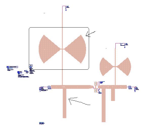
do anyone have sample of the ADS simulated frequency multiplier file? I would like to study some method on how to draw a frequency doubler schematic on the ADS.
 

i have one , but it is for my master thesis , i will send u some files

what do u want extactly inn the multiplier ?

khouly
 

    t_tuaki

    Points: 2
    Helpful Answer Positive Rating
actually I want to simulate the graph of output power vs input power, HB, gain conversion and so on. But I don't know how to do it with ADS. And regarding to a diagram if it mentioned the input power level Pin is set to 1 dBm, how can I set in ADS? Because what I do is normally terminate it with 50 ohm only and did not do with power. Thanks for help.
 

u need to make the HB engine work for multiplie harmonics , and draw the second or the third harmonic of the output

then u can a sweep paramter component to sweep the input power and draw the output power

i am preparing a simple file , to show u the steps

khouly
 
thanks. you help me what i need. and i still have problem. in the file u upload, how you create the microstrip in schematic? i upload the schematic and show the arrow there. what i done before never use this. I want to know how to create it. And how to convert it into the layout?


it called circuit EM co simulation , i draw the layout , and make it as component , and make momentum which is the EM simulator in ADS package , simulate the microstrip sttucture and include its effects in the circuit simulation , to get the best accuracy

by the way i have fabricated and measured this multiplier and it gives a very good agrement between simulation and measurments results

khouly
 

    t_tuaki

    Points: 2
    Helpful Answer Positive Rating
but is it any different if i use microstrip component available to draw out and then generate the layout due to i still don;t know more to create the shape and make it into schematic? will the result big different? although i already learn some basic lab session, but i still have many doubt.
1. the traingle shape in your schematic is represent what?
2. how you measure the size of all the layout so accurately in schematic?
 

the layout component is an accurate component used

so it is acccuray is like true layout

about the triangle , it is not , it is a radial stub

khouly
 

    t_tuaki

    Points: 2
    Helpful Answer Positive Rating
why and when should use radial stub? what i see before is use open stub or short stub in the schematic.
your layout radial stub is it equivalent to the component below?
 

yeah , the stubs in my design is the layout equivalent of this schematic

khouly
 

when is the time for us to use radial stub instead others?
 

the radial sybs can be used in bias tees design , where they can be used instead of the Lmada/4 open ended stub

khouly
 
i would like to ask the equation in the file u attached.

output_power=dBm(vout[::,2])
conversion gain=output_power-PIN

can you explained the [::,2]?
and the conversion gain formula is it fix for all the multiplier? why all the value is minus PIN? the frequency you wan tested is -4Ghz?

Where can find out more about info about conversion gain?
 

this formula make ADS calculate the power of the second harmonic , which is the frequqncy component u want

PN is the input power , u need to defined this varibale in schematic and make sweep on it

and the conversion gain is the output power - PIN

khouly
 

    t_tuaki

    Points: 2
    Helpful Answer Positive Rating
in IEEE there is a paper for multiplier design, simulation files of ADS is add in this file. these files are uploaded as multimedia with paper.
it is a good start.
I forgot name of paper
 

    t_tuaki

    Points: 2
    Helpful Answer Positive Rating
is it the paper called "Active frequency multiplier design using cad"??

i have the paper but I couldn't get the simulation of ADS file. Can you help me?
 

would u upload the paper here ?

khouly
 

    t_tuaki

    Points: 2
    Helpful Answer Positive Rating
Active frequency multiplier design using cad

can help to get the ads file and the multimedia file as stated by has_ajam?
 

yes, I have downloaded it an hour ago!!
Have you access to IEEE?
you can search the paper and click on multimeadia
there is a zip file 4.8MB.
it is havy for me but I will try to upload it.

Added after 4 minutes:

this is the ADS file of paper
 

    t_tuaki

    Points: 2
    Helpful Answer Positive Rating
Status
Not open for further replies.

Part and Inventory Search

Welcome to EDABoard.com

Sponsor

Back
Top